L8-4 Hoist Circuit Component Repair L08031
Assembly
1. Coat all parts including housing bores with clean
type C-4 hydraulic oil. Lubricate O-rings lightly
with a multipurpose grease.
2. If restrictor poppet (2, Figure 8-6) was removed,
reassemble in the order shown.
3. Install poppets (11, Figure 8-5) in their respec-
tive bores. Install springs (12).
4. Install O-rings (10), and cover (13). Install cap-
screws (14). Tighten capscrews to 60 ft. lbs.
(81 N.m) torque.
5. Install low pressure relief (7) in sleeve (6) and
install assembly in housing (9). Install main
relief valve (4). Install springs (3 & 5). Install
cover (2). Install capscrews (1). Tighten cap-
screws to 60 ft. lbs. (81 N.m) torque. Connect
external tube, tighten nuts to 25 ft. lbs. (34
N.m) torque.
SPOOL SECTION
Disassembly
NOTE: It is not necessary to remove the inlet
sections (4, Figure 8-2) to accomplish spool section
(3) disassembly.
1. Match mark or identify each part when removed
in respect to its location or respect to its mating
bore to aid reassembly.
2. Remove capscrews and remove spool section
cover (2, Figure 8-2). Remove and discard O-
rings (4 & 5, Figure 8-8).
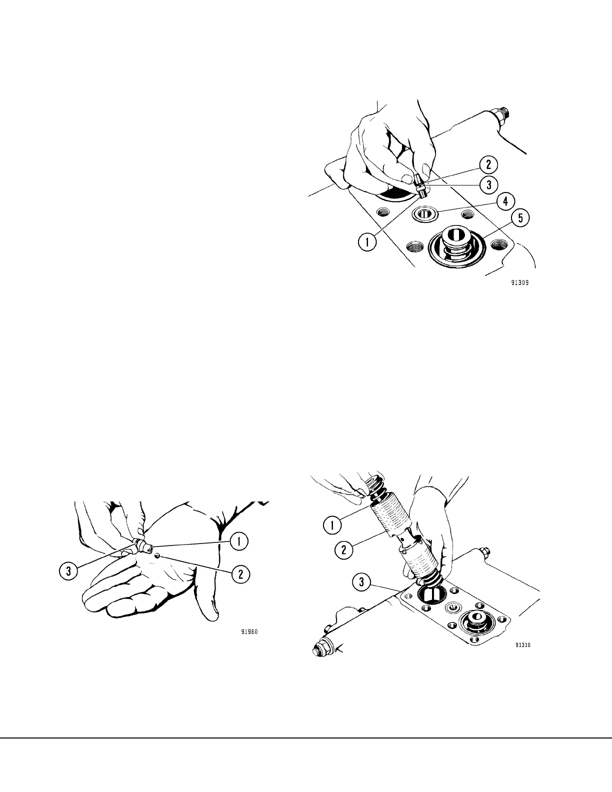
3. Remove poppet (1, Figure 8-7), remove and dis-
card O-ring (3).
NOTE: The poppet (1) is equipped with a small steel
ball. Do not misplace.
4. Remove restrictor poppet (1, Figure 8-8).
Remove and discard O-ring (2) and backup ring
(3), if used. Note the position of the restrictor
when removed to insure correct reassembly.
5. Remove spool assembly (2, Figure 8-9). Note
the color of the lower spring (blue) to insure
proper location during reassembly. Also note
the “V” groove (1) on end of spool.
FIGURE 8-7. POPPET & BALL
1. Poppet
2. Steel Ball
3. O-Ring
1. Restrictor Poppet
2. O-ring *
3. Backup Ring *
4. Seal Ring
5. O-Ring
*Note: Items 2 & 3 not used on all valves.
FIGURE 8-8. RESTRICTOR POPPET REMOVAL
1. “V” Groove
2. Spool Assembly
3. Spool
FIGURE 8-9. SPOOL REMOVAL