L8-14 Hoist Circuit Component Repair L08031
Cleaning and Inspection
NOTE: Use only fresh cleaning solvent, lint free
wiping cloth and dry filtered compressed air when
cleaning and handling hydraulic cylinder parts.
Immediately after cleaning and inspection, coat all
surfaces and parts with clean hydraulic oil (Type C-
4).
1. Thoroughly clean and dry all parts.
2. Visually inspect all parts for damage or exces-
sive wear.
3. If cylinder bores or plated surfaces are exces-
sively worn of grooved, the parts must be
replaced or, if possible, re-plated and machined
to original specifications.
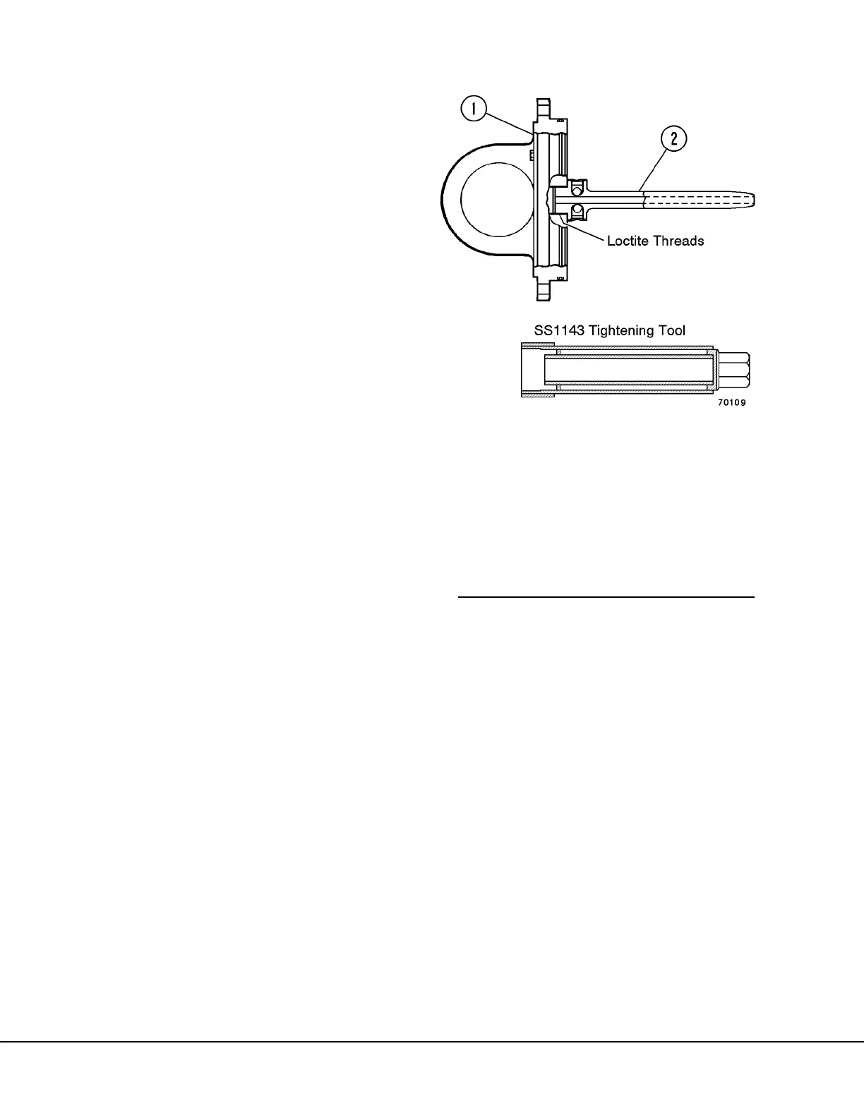
4. The quill (2, Figure 8-19) should be checked for
tightness if it has not previously been tack
welded.
a. Check the quill for tightness by using special
tool SS1143 (Figure 8-19) and applying a
tightening torque of 1000 ft. lb. (1356 N.m).
b. If the quill moves, remove quill, clean
threads in cover assembly and quill, and
reinstall using the procedure in “Quill Instal-
lation”.
5. When a cylinder assembly is dismantled, the
capscrews (7, Figure 8-18) should be checked
carefully for distress and, if in doubt, replace
them.
SS1143 Tightening Tool - Assembly Drawing
S1144 – Square Tube
(3.50" x 3.50" x 0.19" wall x 2.0" long)
SS1145 – Plate
(2.50" x 2.50" x 0.25" thick)
SS1146 – Square Tube
(3.00" x 3.00" x 0.25" wall x 15.50" long)
SS1147 – Tube, Brass
(1.75"O.D. x 1.50" I.D. x 13.50" long)
SS1148 – Square Cut
(2.50" x 2.50" x 0.75" thick)
SS1149 – Hex Drive
(1.75" Hex stock x 2.50" long)
All materials are 1020 Steel except SS1147.
1. Cap Assembly 2. Quill Assembly
FIGURE 8-19. QUILL INSTALLATION