L08031 Hoist Circuit Component Repair L8-15
ASSEMBLY OF QUILL AND CYLINDER
NOTE: Use only new seals, bearings and O-rings
during reassembly. Thoroughly lubricate all parts and
seals with hydraulic oil to aid in assembly and to
provide lubrication during initial operation.
Quill Installation
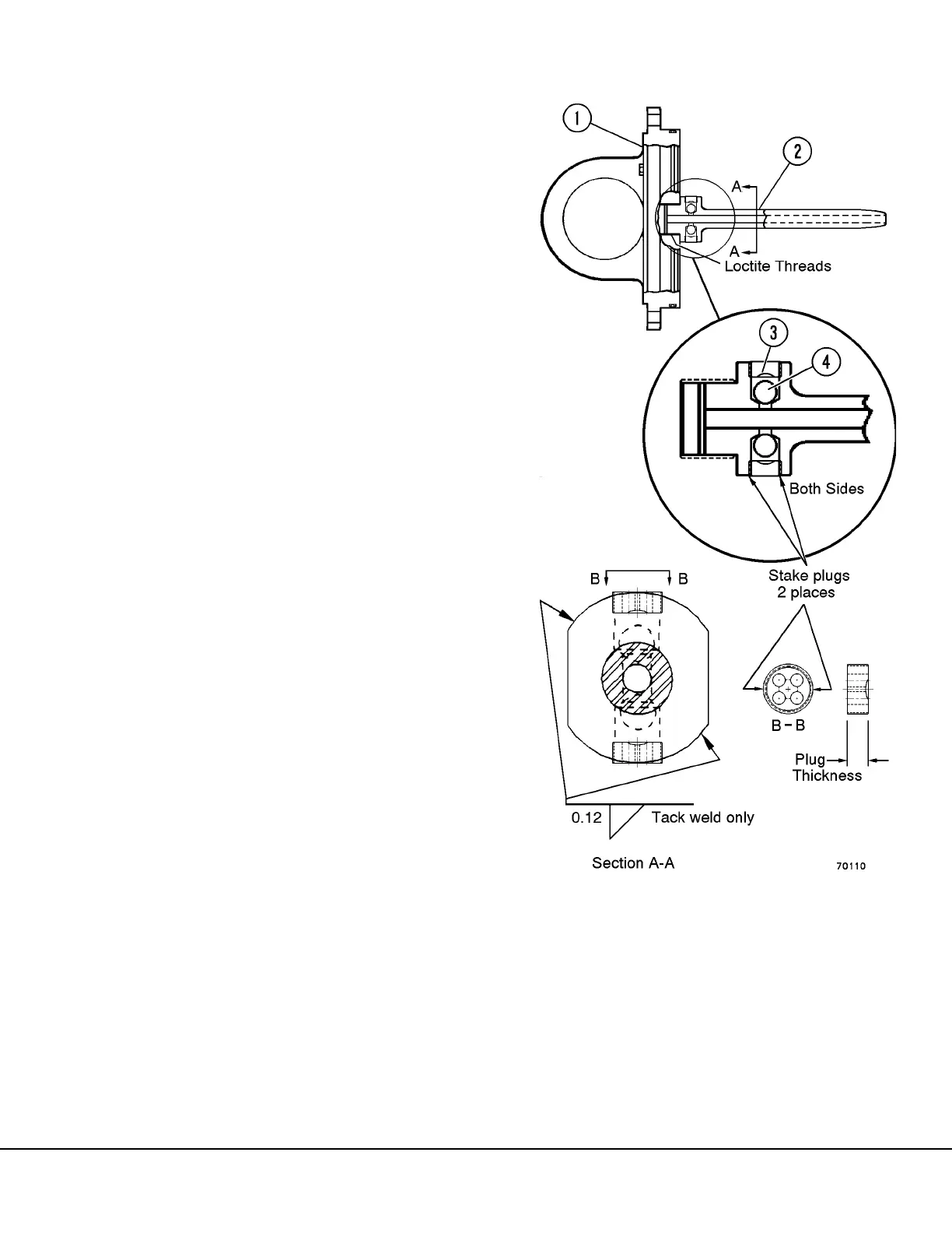
1. The plugs (3, Figure 8-20) and the check balls
(4) in the quill should be checked during any
cylinder repair to insure the plugs are tight and
ball seats are not damaged. Refer to “Installa-
tion of Check Balls and Plugs in Quill”.
2. Secure cap assembly (1) in a sturdy fixture.
Make certain threads in cap and threads on quill
are clean and dry (free of oil and solvent).
3. Using Loctite “LOCQUIC” Primer “T” (TL8753, or
equivalent), spray mating threads of both cap
assembly (1) and quill assembly (2). Allow
primer to dry 3 to 5 minutes.
4. Apply Loctite Sealant #277 (VJ6863, or equiva-
lent) to mating threads of both cap assembly
and quill assembly.
5. Install quill and use SS1143 tool to tighten quill
to 1000 ft. lbs. (1356 N.m) torque. Allow parts
to cure for 2* hours before exposing threaded
areas to oil.
* Note: If “LOCQUIC” primer “T” (TL8753) was not
used, the cure time will require 24 hours instead of 2
hours.
6. Tack weld quill in 2 places as shown in Figure 8-
20.
7. Remove all slag and foreign material from tack
weld area before assembly of cylinder.
During future cylinder rebuilds, removal of the quill
will not be necessary, unless it has loosened or is
damaged. Removal, if necessary, will require a
break-loose force of at least 2000 ft. lbs. (2712 N.m)
torque after the tack welds are ground off.
1. Cap Assembly
2. Quill Assembly
3. Plug
4. Check Ball
FIGURE 8-20. PLUG & CHECK BALL
INSTALLATION