C2-2 Power Module 6/02 C02018
4. Remove clamp and remove the outlet hose to rear
axle on the blower assembly.
5. Disconnect all (already marked) electric, air, oil
and fuel lines that would interfere with power
module removal. Cover or plug all lines and their
connections to prevent entrance of dirt or foreign
material. To simplify this procedure, most connec-
tions utilize quick disconnects.
6. Disconnect the air cleaner restriction gauge
hoses. Disconnect electrical wiring and hoses
etc. that would interfere with front center deck
removal.
7. Remove air inlet duct support rods on underside
of center deck.
8. Attach hoist to the front center deck. Remove all
capscrews, flat washers, lockwashers and nuts
securing the deck. Check for any remaining wir-
ing, hoses or other items on underside of deck.
Lift deck and remove from truck.
9. Close both cab heater shutoff water valves dis-
connect water lines and drain water from the
heater core. Secure water lines away from engine
compartment so as not to interfere with power
module removal.
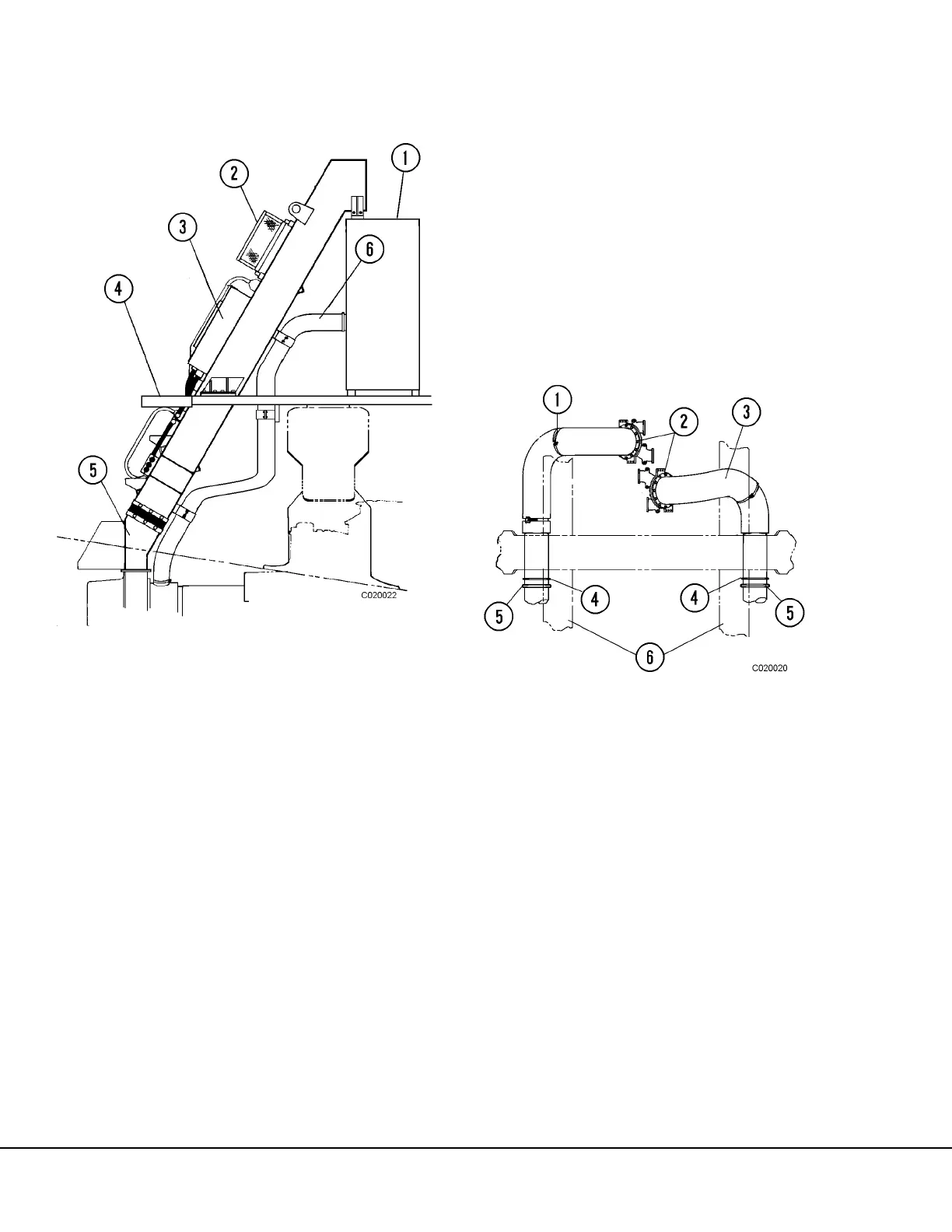
10. Remove capscrews (2, Figure 2-2) and nuts secur-
ing left (1) and right (3) exhaust ducts to turbo-
charger outlets. Remove “V” band clamps (5) and
support clamps (4). Remove exhaust ducts and
move clear of engine. Cover turbocharger
exhaust openings to prevent entrance of foreign
material.
11. Remove clamps (6, Figure 2-3) securing the air
intake ducts (3) to turbochargers (4). Remove
clamps at hump hoses (1). Remove air intake
ducts and cover inlets on turbochargers and ducts
to air cleaners.
FIGURE 2-1. MAIN ALTERNATOR BLOWER DUCT
FIGURE 2-2. EXHAUST DUCTS
(Heated Body Exhaust & 2 Stage Turbochargers
Shown)
1. Electrical Cabinet
2. Resistor Panel (2)
3. Rectifier Diode Panel
4. Rear, Center Deck
5. Transition Str.
6. Air Hose
1. LH Exhaust Duct
2. Capscrews
3. RH Exhaust Duct
4. Support Clamp
5. “V” Band Clamp
6. Frame Rails