C02018 6/02 Power Module C2-3
12. Remove upper radiator support struts (12, Figure
2-4).
13. Disconnect grounding strap located near the front
subframe mount.
14. Remove capscrews and washers securing cover
(10, Figure 2-4) to grille at center of front bumper
and remove. Remove capscrews and lockwash-
ers (9) securing front subframe support to main
frame.
Install safety chain around the front engine sub-
frame cross member and main frame to prevent the
power module from rolling forward when the sub-
frame rollers are installed.
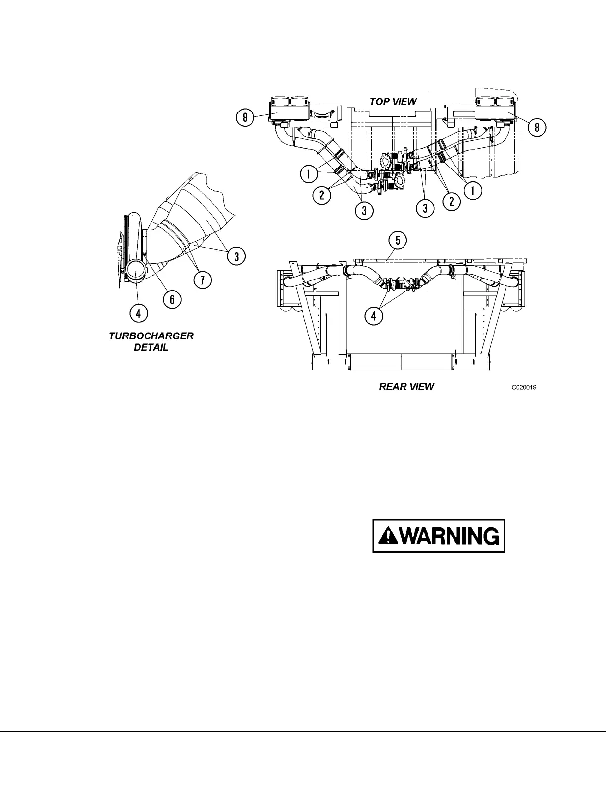
FIGURE 2-3. AIR INTAKE DUCTS
Note: Illustration shows engine
equipped with two-stage turbo-
chargers. Single stage turbo-
charger equipped engine ducts
and supports are similar.
1. Hump Hose
2. Support Rods
3. Air Intake Ducts
4. Turbocharger
5. Center Deck Str.
6. Clamp
7. T-Bolt Clamp
8. Air Cleaner Assembly