C2-4 Power Module 6/02 C02018
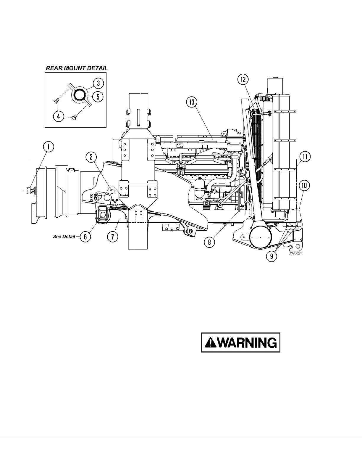
15. Remove capscrews (4, Figure 2-4) and caps (3)
securing subframe mounting bushings to the sub-
frame support bracket (6) at rear of subframe.
16. Check engine and alternator to make sure all
cables, wires, hoses, tubing and linkages have
been disconnected.
Only lift power module at the lifting points on sub-
frame and engine/alternator cradle structure. (Refer
to Figure 2-6.)
17. Attach hoist to lift points (2, Figure 2-4) at engine/
alternator cradle structure. Raise the rear portion
of engine subframe and install subframe rollers
(Refer to Figure 2-5). Lower the rear portion of the
subframe carefully until the rollers rest on the
main frame guide rail.
FIGURE 2-4. ENGINE MODULE INSTALLATION
1. Pump Driveshaft
2. Rear Module Lift Eye
3. Cap
4. Capscrews
5. Bushing
6. Rear Subframe Mount Bracket
7. Module Subframe
8. Front Module Lift Eye
9. Front Mount Capscrews
10. Cover
11. Grille Str.
12. Upper Radiator Support Rod
13. Engine