Commissioning
25
Pos: 14.15 /Übersc hriften/Überschri ften 2/F-J/Gelenkwel le @ 0\mod_1199781879794_ 78.docx @ 34542 @ 2 @ 1
5.4 PTO shaft
Pos: 14.16 /Übersc hriften/Überschri ften 3/K-O/Längenanpa ssung @ 1\mod_12016876328 10_78.docx @ 53589 @ 3 @ 1
5.4.1 Length adjustment
Pos: 14.17 /BA/Er stinbetriebnahme/Gelen kwelle/Mähwerke/Lä ngenanpassung Bild EC 2800/3200 @ 10\mod_12218 14571820_78.doc x @ 138104 @ @ 1
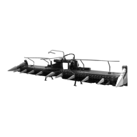
EC-0-026
Figure 5
Pos: 14.18 /BA/Er stinbetriebnahme/Gelen kwelle/Mähwerke/A nbau Gelenkwelle al lgemeiner Text EC 2800/320 0 @ 10\mod_1221815490726_78. docx @ 138170 @ @ 1
The ends of the PTO shaft which has been provided are equipped with a longer and a shorter
guard over the joints. The joint with the longer guard must be pushed onto the gear input shaft
towards the machine.
Pos: 14.19 /BA/Er stinbetriebnahme/Gelen kwelle/Mähwerke/Lä ngenanpassung_ohne Pf ahlsicherung @ 10\mod_ 1221813873039_78. docx @ 138060 @ @ 1
The length of the PTO shaft (1) must be adjusted.
• Disassemble the PTO shaft.
• Install each half (1) and (2) on the tractor and machine side respectively.
• Check the special section tubes and guard tubes.
• Shorten special section tubes and guard tubes to an extent that the PTO shaft can move
freely in the shortest operating position.
• For additional operating instructions refer to the operating instructions of the PTO shaft
manufacturer.
Pos: 14.20 /Layout Module /---------------Seitenumbruch---------------- @ 0\mod_1196175311226_0.docx @ 4165 @ @ 1

 Loading...