12. - Appendix
GMD16-GMD20
87
KN225BGB_A
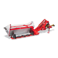
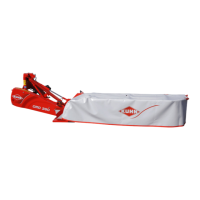
Disc mower
12. Appendix
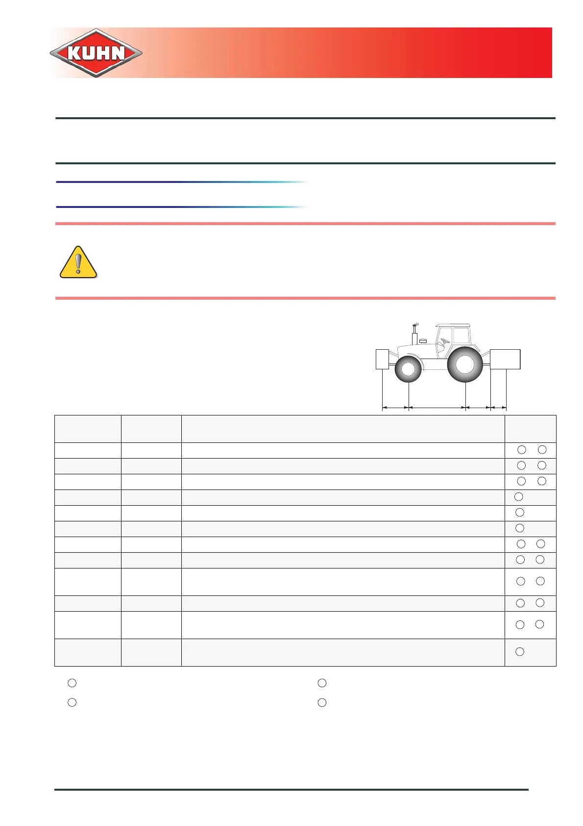
12.1 Calculating the load on an axle
When coupling a tool to the front and/or rear 3-point lift linkage, the maximum authorized
payload must not be exceeded.
The load on the tractor front axle must always represent 20 % of the tractor unladen weight.
Prior to use, check that these conditions are satisfied by making this calculation or by weighing
the tractor-machine unit.
Define the total weight, axle loads, tyre
capacity and minimum additional mass:
The following values are required for the
calculation:
Description Units Description
Obtained
by
T kg Tractor unladen weight
T1 kg Unladen load on tractor front axle
T2 kg Empty load on tractor rear axle
t kg Axle loads (Tractor + machine)
t1 kg Load on front axle (Tractor + machine)
t2 kg Load on rear axle (Tractor + machine)
M1 kg Total weight of front tool or front ballast
M2 kg Total weight of rear tool or rear ballast
am
Distance between the tools' centre of gravity or the front ballast and the
front axle centre
b m Distance between the tractor axles
cm
Distance between the rear axle center and the center of the lower link ball
joints
d m
Distance between the centre of the lower link ball joints and the centre of
gravity of the rear tool or rear ballast
M1
abcd
T
1
T2
M2
4
1
4
4
4
2
3
2
3
1
2
Refer to the tractor operators' manual
Refer to the machine price-list or operators'
manual
Dimensions Measure on scale
4
 Loading...