Appendix A
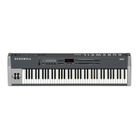
SP2 Specifications
Audio Specifications
Line-Level Left and Right Analog Audio Outputs
Connectors
Balanced outputs using two 1/4-inch stereo ( tip-ring-sleeve ) phone plugs
and shielded twisted pair cable or unbalanced using two 1/4-inch mono (tip-
ring) phone plugs and coaxial cable.
400 ohm, Balanced, nominal
Impedance
200 ohm, Unbalanced, nominal
20.8 dBu (8.5 Volts RMS) Balanced, high-impedance load
Maximum output level
14.7 dBu (4.2 Volts RMS) Unbalanced, high-impedance load
Frequency Response 20Hz–20kHz +/– 0.6 dB
Idle channel noise
Less than -115 dBA, balanced, relative to full-scale signa
l
Dynamic Range Greater than 112 dBA, balanced, using -60 dBFS signal
Stereo Channel
Separation
96 dB
Headphone Output
Output impedance 47 Ohm, nominal
Maximum output level -4 dBu ( 0.5 Volts RMS ) with 32 Ohm load
Parameter Reference
Parameter
Group
Subgroup
(if any)
Parameter Range of Values Default
Lo C-1–G 9 G#3(Ab3)
Hi C-1–G 9 G 9
Key Range
Note Map Linear Linear
Transposition Transpose -24 to 24 0
Vel Min 1–127 1
Velocity
Vel Max 1–127 127
Continuous
controllers
Wheel 1
Up/Down
2 Semitone
Wheel 1 Up/Down
Ctrl Num : Pitch Up
Wheel 2
Wheel 2 Ctrl Num:
Mod Wheel
Knob A Ctrl Num : 6
Knob B Ctrl Num : 13
Knob C Ctrl Num : 22
Knob D Ctrl Num : 23
These controllers
all have the same
three Parameters,
called the Basic
Parameter Group.
Usually the same,
of Ctrl Num; its
value varies for
each controller
Pedal 1
Exit Value None, 0–127 (default None)
Ctrl Num : 11
A-2

 Loading...