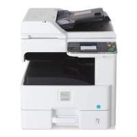
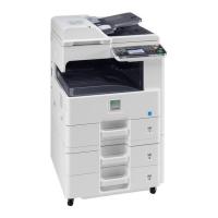
2K3/2L3
2-3-11
YC12 1 GND - - Ground
Connected to
developing
relay
PWB,RFID
PWB,toner
sensor,toner
container
lock sensor
and toner
container
switch
2 DLP_SDA I/O 0/3.3 V DC(pulse) DEVPWB EEPROM data signal
3 DLP_SCL O 0/3.3 V DC(pulse) DEVPWB EEPROM clock signal
4 3.3V4 O 3.3 V DC 3.3 V DC power output to DEVPWB
5 GND - - Ground
6 RFID_SDA I/O 0/3.3 V DC(pulse) RFPWB EEPROM data signal
7 RFID_SCL O 0/3.3 V DC(pulse) RFPWB EEPROM clock signal
8 3.3V4 O 3.3 V DC 3.3 V DC power output to RFPWB
9 3.3V4 O 3.3 V DC 3.3 V DC power output to TS
10 TON_EMP I 0/3.3 V DC TS: On/Off
11 GND - - Ground
12 3.3VLED O 3.3 V DC 3.3 V DC power output to TCLS
13 GND - - Ground
14 CON_LOCK I 0/3.3 V DC TCLS: On/Off
15 TCONSET I 0/3.3 V DC TCSW: On/Off
16 GND - - Ground
YC13 1 3.3VLED O 3.3 V DC 3.3 V DC power output to HPS
Connected to
home
position
sensor,origin
al detection
switch and
original size
sensor
2 GND - - Ground
3 SCA_HP I 0/3.3 V DC HPS: On/Off
4 3.3VLED O 3.3 V DC 3.3 V DC power output to ODSW
5 GND - - Ground
6 SCA_COVER I 0/3.3 V DC ODSW: On/Off
7 GND - - Ground
8 SCA_SIZE O 0/3.3 V DC OSS: On/Off
9 5V4 I 5 V DC 5 V DC power output to OSS
YC14 1 SCANNER B1 O 0/24 V DC(pulse) ISUM drive control signal
Connected to
ISU motor
2 SCANNER A2 O 0/24 V DC(pulse) ISUM drive control signal
3 SCANNER B2 O 0/24 V DC(pulse) ISUM drive control signal
4 SCANNER A1 O 0/24 V DC(pulse) ISUM drive control signal
Connector Pin Signal I/O Voltage Description

 Loading...
