2GZ/2G1-2
2-1-13
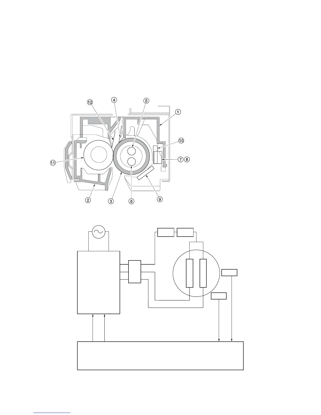
2-1-7 Fuser section
The fuser section consists of the parts shown in figure. When paper reaches the fuser section after the transfer process, it
passes between the press roller and heat roller, which is heated by fuser heaters M or S (FH-M or FH-S). Pressure is
applied by the fuser unit pressure springs so that the toner on the paper is melted, fused and fixed onto the paper. The
heat roller is heated by fuser heaters M or S (FH-M or FH-S) inside it; its surface temperature is detected by the fuser unit
thermistor 1 and 2 (FTH1/2), and is regulated by the fuser heaters turning on and off.
If the fuser section becomes abnormally hot, fuser unit thermostat 1 and 2 (FTS1/2) operates shutting the power to the
fuser heaters off. When the fusing process is completed, the paper is separated from the heat roller by its separation claws
and is conveyed from the machine to eject and switchback section.
Figure 2-1-19 Fuser section
Figure 2-1-20 Fuser section block diagram
(1) Upper fuser unit cover
(2) Fuser housing
(3) Heat roller
(4) Heat roller separation claws
(5) Fuser heater M (FH-M)
(6) Fuser heater S (FH-S)
(7) Fuser unit thermostat 1 (FTS1)
(8) Fuser unit thermostat 2 (FTS2)
(9) Fuser unit thermistor 1 (FTH1)
(10) Fuser unit thermistor 2 (FTH2)
(11) Press roller
(12) Press roller separation claws
FH-M
FH-S
FTS1FTS2
FH-M ON
FH-S ON
YC1-5
YC1-4
EPWB
YC10-A6
FTH1
YC10-A10
FTH2
FTH1
FTH2
YC5-1
YC5-3
YC5-2
PSPWB
YC2-2
YC2-3
Heat roller
ILSW
 Loading...