EasyManua.ls Logo

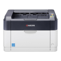
Kyocera FS-2020D Service Manual

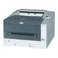
Kyocera FS-2020D
135 pages
To Next Page IconTo Next Page
Page #1 background imageLoading...
Page #1 background image
SERVICE
MANUAL
Published in March 2010
2J2SM065
Rev. 5
FS-2020D
FS-3920DN
FS-4020DN

Table of Contents

Other manuals for Kyocera FS-2020D

Questions and Answers:

Kyocera FS-2020D Specifications

General IconGeneral
ColorNo
Duplex printingYes
Print technologyLaser
Maximum resolution1200 x 1200 DPI
Time to first page (black, normal)9 s
Print speed (black, normal quality, A4/US Letter)35 ppm
Memory typeDDR2
Processor modelPowerPC 440
Maximum internal memory1152 MB
Sound power level (standby)29 dB
Sound pressure level (printing)52 dB
Power supply type220/240 V, 50/60 Hz
Capacity cartridge12000 sheets
Power consumption (active)560 W
Recommended monthly print volume20000 pages
Maximum duty cycle150.000 pages per month
Number of print cartridges1
Total input capacity500 sheets
Total output capacity250 sheets
Maximum input capacity1100 sheets
Maximum number of input trays2
Multi-Purpose tray input capacity100 sheets
Maximum print size216 x 356 mm
Paper tray media typesPlain paper, Recycled paper
Paper tray media weight60 - 120 g/m²
Non-ISO print media sizesLetter
ISO A-series sizes (A0...A9)A4, A5, A6
ISO B-series sizes (B0...B9)B5
Maximum ISO A-series paper sizeA4
Multi-Purpose Tray media weight60 - 220 g/m²
AC input voltage220 - 240 V
AC input frequency50 - 60 Hz
Power consumption (standby)9.2 W
Power consumption (PowerSave)5.7 W
Energy Star Typical Electricity Consumption (TEC)2.6 kWh/week
DisplayLCD
CertificationGS, TüV, CE
Standard interfacesParallel, USB 2.0
Optional connectivityEthernet, Wireless LAN
Sustainability certificatesENERGY STAR
Weight and Dimensions IconWeight and Dimensions
Dimensions (WxDxH)382 x 394 x 285 mm

Summary

Safety Precautions

Safety Warnings and Precautions

Explains hazard levels (DANGER, WARNING, CAUTION) and safety symbols used.

1-1 Specifications

1-1-1 Specifications

Detailed technical specifications for printer models.

1-1-2 Parts Names

Identification and listing of printer components.

1-1-3 Machine Cross Section

Diagrams showing internal printer structure and component layout.

1-2 Installation

1-2-1 Installation Environment

Requirements for optimal printer setup location and conditions.

1-2-2 Unpacking

Procedure for safely removing the printer from its packaging.

1-2-3 Installing Expanded Memory (Option)

Steps to install optional memory modules.

1-2-4 Installing Memory Card (Option)

Steps to install optional memory cards.

1-3 Maintenance Mode

1-3-1 Maintenance Mode

Accessing and using the printer's service and diagnostic functions.

1-3-2 Contents of Maintenance Mode Items

Detailed explanation of available maintenance functions.

1-4 Troubleshooting

1-4-1 Paper Misfeed Detection

Diagnosing and resolving paper jam issues.

1-4-2 Self-Diagnostic Function

Understanding and using printer error codes for diagnosis.

1-4-3 Image Formation Problems

Identifying and correcting print quality issues.

1-4-4 Electric Problems

Troubleshooting electrical faults and error messages.

1-5 Assembly and Disassembly

1-5-1 Precautions for Assembly and Disassembly

Safety guidelines for handling printer parts during maintenance.

1-5-2 Outer Covers

Procedures for removing and replacing external printer covers.

1-5-3 Paper Feed Section

Disassembly and reassembly of paper feeding mechanisms.

1-5-4 Developing Section

Steps for removing and installing the developing unit.

1-5-5 Drum Section

Procedures for detaching and refitting the drum unit.

1-5-7 Fuser Section

Procedures for removing and replacing the fuser unit and its parts.

1-5-8 PWBs

Instructions for removing and installing Printed Circuit Boards (PWBs).

1-6 Firmware

1-6-1 Downloading Firmware

Process for updating printer firmware via USB or memory card.

1-6-2 Downloading Firmware from USB Memory

Specific steps for firmware update using a USB drive.

2-1 Mechanical Construction

2-1-1 Paper Feed Section

Mechanical details of the paper feeding system.

2-1-2 Drum Section

Mechanical details of the drum unit and its components.

2-1-3 Expose Section

Mechanical details of the laser scanner unit.

2-1-4 Developing Section

Mechanical details of the developing unit and toner system.

2-1-7 Fuser Section

Mechanical details of the fuser unit and its heating system.

2-1-8 Paper Exit Section/Rear Unit

Mechanical details of paper exit and rear unit components.

2-2 Electrical Parts Layout

2-2-1 Electrical Parts Layout

Diagrams showing the location of electrical components.

2-3 Operation of the PWBs

2-3-1 Power Source PWB

Block diagram and function of the power source PWB.

2-3-2 Engine PWB

Block diagram and function of the engine PWB.

2-4 Appendixes

Repetitive Defects Gauge

Chart showing distances for common recurring print defects.

Wiring Diagram (35 ppm Printer)

Electrical wiring schematics for the 35 ppm model.

Wiring Diagram (40 ppm Printer)

Electrical wiring schematics for the 40 ppm model.

Wiring Diagram (45 ppm Printer)

Electrical wiring schematics for the 45 ppm model.

Related product manuals