2DF
1-3-26
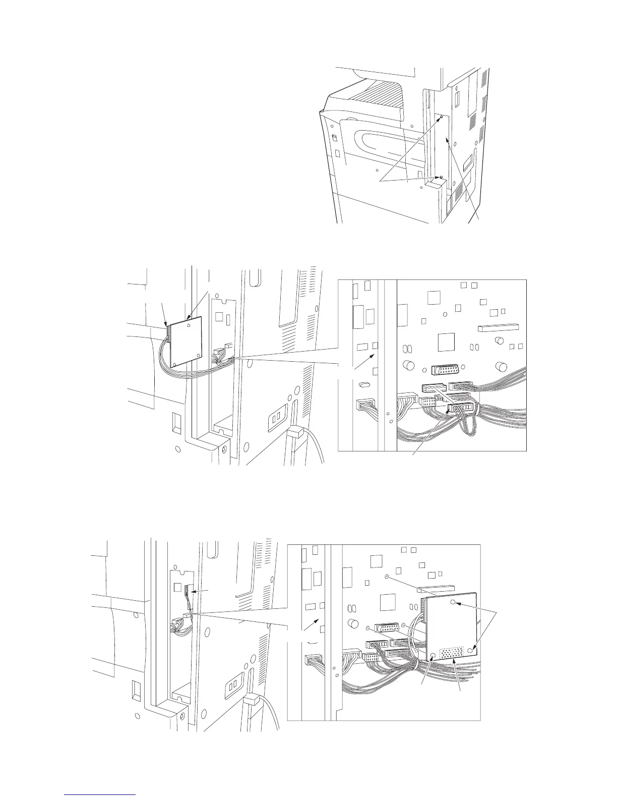
Figure 1-3-40
Figure 1-3-41
Figure 1-3-42
7. Remove the two screws securing the shield
cover and then the cover.
8. Detach the 10-pin connector (four wires) from
CN4 on the main PCB and connect it to J2 on
the IPC PCB.
9. Connect J1 on the IPC PCB to CN15 on the
main PCB.
10. Insert the three board supports of the IPC
PCB into the main PCB to secure them.
11. Refit the shield cover.
Shield cover
Screws
J2
CN4
CN15
Main PCB
10-pin connector
IPC PCB
10-pin connector

 Loading...


