2DF
1-3-35
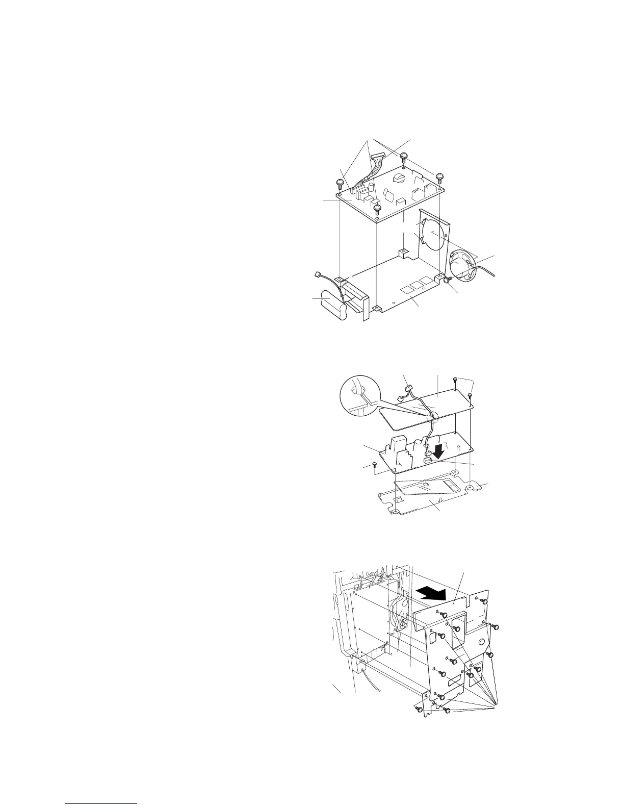
Figure 1-3-66
Rear cover
Screws
1-3-10 Installing the Facsimile System (option)
Procedure
1. Fit the battery pack into the NCU retainer as
shown in the illustration.
2. Fit the speaker onto the two catches on the
NCU retainer, and fasten it into place with
one M3 × 06 chrome binding screw.
3. Fasten the NCU board to the NCU retainer
with four M3 × 06 chrome binding screws.
4. Connect the NCU cable to connector CN1 on
the NCU board.
Figure 1-3-64
Figure 1-3-65
5. Adhere the lower-sheet to the auxiliary power
source retainer.
6. Fasten the auxiliary power source PCB,
together with the upper-sheet, to the auxiliary
power source retainer, using three M3 × 06
chrome binding screws.
7. Pass the FAX-PCB-Power cable through the
cutout in the upper-sheet, and connect it to
connector CN1 on the auxiliary power source
PCB.
Connector
CN1
M3 × 06 chrome
binding screws
NCU board
Battery pack
NCU retainer
M3 × 06 chrome binding screw
Speaker
NCU cable
Catches
Connector CN1
M3 × 06 chrome
binding screws
Upper-sheet
FAX-PCB-Power cable
Auxiliary power
source PCB
M3 × 06 chrome
binding screw
Lower-sheet
Auxiliary power
source retainer
8. Remove 13 screws and take off the rear
cover.

 Loading...


