2A3/4
3-6-14
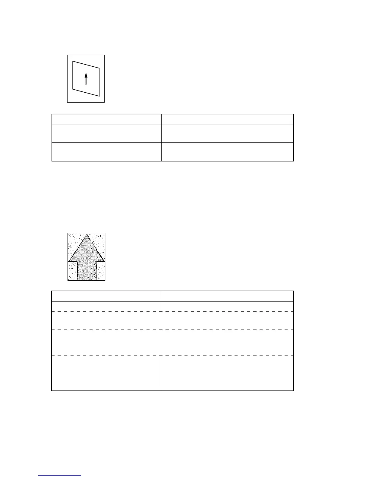
(19) Image is not square.
Causes
1. Laser scanner unit positioned incorrectly.
2. Image scanning unit positioned incorrectly.
Causes Check procedures/corrective measures
1. Laser scanner unit positioned
incorrectly.
2. Image scanning unit positioned
incorrectly.
Adjust the installation position of the laser
scanner unit (see page 3-3-33).
Adjust the installation position of the image
scanning unit (see page 3-3-35).
(20) Image contrast is low
(carrier scattering).
Causes
1. No developing bias output.
Causes Check procedures/corrective measures
1. No developing bias output.
A. Developing bias wire makes poor
contact.
B. Defective main PCB.
C. Defective high-voltage
transformer PCB.
Check the developing bias wire. If there are
any problems, replace it.
Check if CN1-85 on the main PCB goes low
when maintenance item U030 is run. If not,
replace the main PCB.
Check if developing bias is output when there
is no problem with the main PCB while
maintenance item U030 is run. If not, replace
the high-voltage transformer PCB.

 Loading...


