2KN/2KP
1-5-50
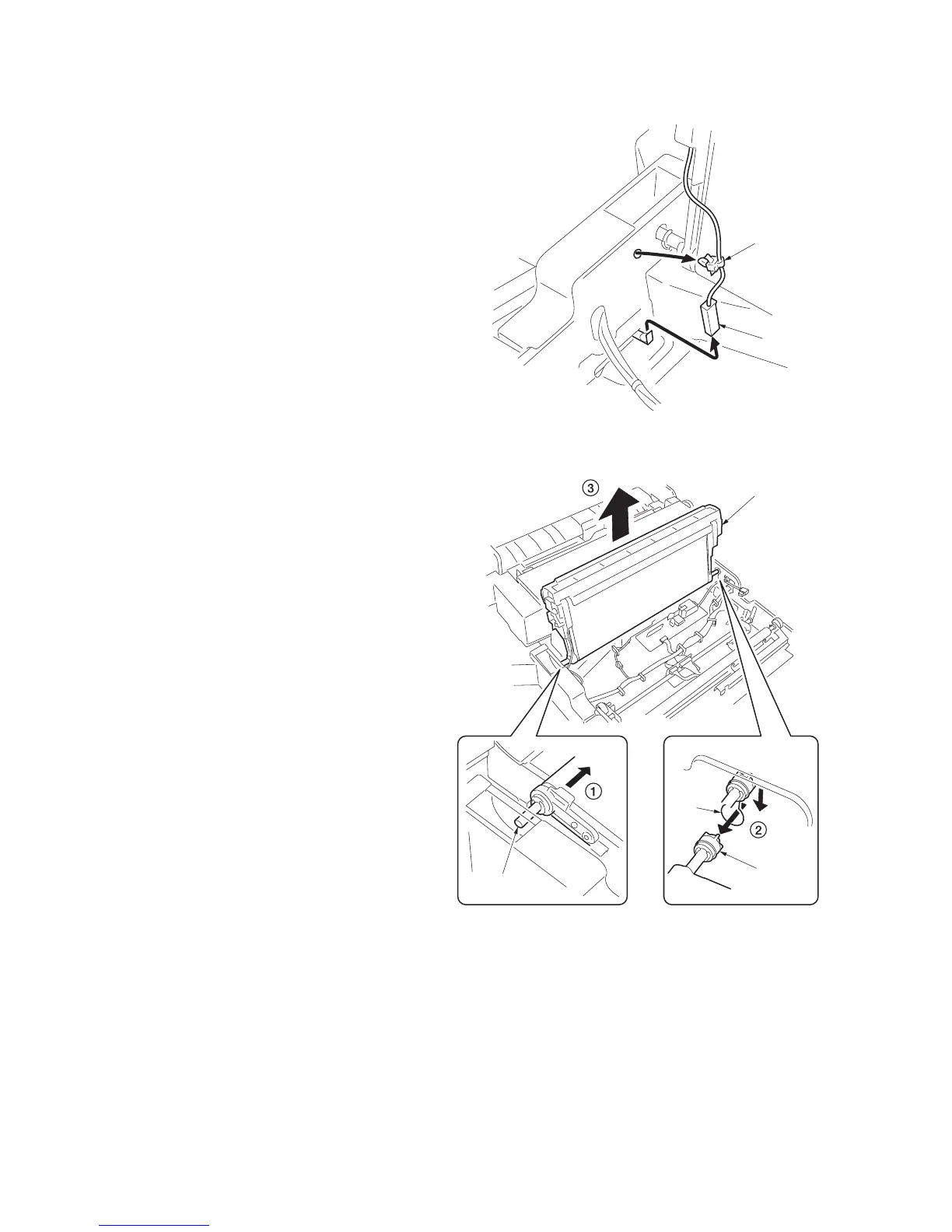
5. Remove the connector and band of the
paper conveying unit front.
Figure 1-5-103
6. After sliding the transfer unit to end and pull-
ing out the front shaft from the frame, pull
out the rear coupling from the hole of the
frame as shown in the figure, and remove
the transfer unit from the paper conveying
unit.
7. When the transfer unit is replaced with a
new one, carry out the following procedure.
8. Perform maintenance mode U127 (clearing
the transfer count) (see page 1-3-44).
Figure 1-5-104
Connecto
Band
Transfer unit
Shaft
Coupling
Hole

 Loading...