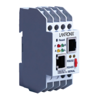
Introduction to XPort™
1.4 Serial Interface
The unit has a serial port that supports RS-232 serial standards (software selectable) up to
230Kbps. The serial interface also provides the +3.3V power, ground, and external reset
signals. The serial signals (pins 4 – 8) are 3.3V CMOS logic level. (NOT 5V tolerant) The
serial signals would normally be connected to an internal device, such as a UART. For
prototype and evaluation work, where an external cable running with RS-232 voltage levels
is required, the XPort™ must be interfaced to a serial transceiver chip. An RS-232
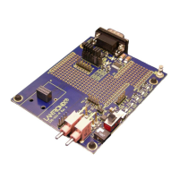
transceiver is supplied on the XPort™ Evaluation board for this purpose.
Table 1 - Serial Interface Signals
SIGNAL
NAME
XPort
™
Pin #
PRIMARY
FUNCTION
GND 1 Circuit Ground
VCC 2 +3.3V Power In
Reset- 3 External Reset In
Data Out 4 Serial Data Out (connects to RX of attached DTE device)
Data In 5 Serial Data In (connects to TX of attached DTE device)
CP1
(Configurable
Pin 1)
6
Configurable Pin 1 can be configured as:
Flow control – connects to CTS of attached DTE device
Programmable Digital Input or Output
Status LED 1
CP2
(Configurable
Pin 2)
7
Configurable Pin 2 can be configured as:
Modem control – connects to DCD of attached DTE device
Programmable Digital Input or Output
CP3
(Configurable
Pin 3)
8
Configurable Pin 3 can be configured as:
Flow control – connects to RTS of attached DTE device
Modem control – connects to DTR of attached DTE device
Programmable Digital Input or Output
Status LED 3
1.5 Ethernet Interface
The Ethernet interface magnetics, RJ-45 connector, and Ethernet status LEDs are all
integrated into the device server shell.
Table 2 - Ethernet Interface Signals
Signal Name DIR Contact Primary Function
TX+ Out 1 Differential Ethernet Transmit Data +
TX- Out 2 Differential Ethernet Transmit Data -
RX+ In 3 Differential Ethernet Receive Data +
RX- In 6 Differential Ethernet Receive Data -
Not Used 4 (Terminated)
Not Used 5 (Terminated)
Not Used 7 (Terminated)
Not Used 8 (Terminated)
SHIELD Chassis Ground
XPort™ User Manual and Development Kit 1-3
 Loading...
