Introduction to XPort™
8
2
71
33.90 [1.335]
1.00 [0.039]
0.35 [0.014]
10.84 [0.427]
6.35 [0.250]
2.54 [0.100] 3.20 [0.126]
0.60 [0.024]
FRONT
SHIELD
GROUND
INTERFACE
PINS
DIMS = mm (in)
11.90 [0.468]
SHIELD TAB
TOLERANCE
.XX+/-0.20[0.008]
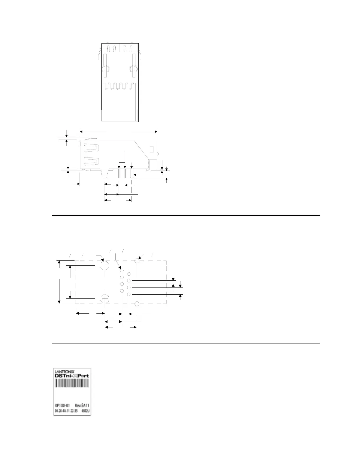
1.8 Recommended PCB Layout
The hole pattern and mounting dimensions for the XPort™ device server are shown in the
following drawing.
16.05
[0.632]
12.30
[0.484]
10.84 [0.427]
6.35 [0.250]
2.54 [0.100]
O
3.25 [ 0.128]
O
O 0.90 [ 0.035]O
1.60[ 0.063]
28
17
1.27 [0.050]
2.54 [0.100]
FRONT
O
11.90 [0.468]
DIMS = mm (in)
SHIELD TAB
TOLERANCE
.XX+/-0.05[0.002]
1.9 Product Information Label
The product information label contains important information about your specific unit.
XPort™ User Manual and Development Kit 1-5

 Loading...