Development Kit
2.6.1 SW1-2 Options
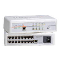
SW1-2 controls the routing of the CP1 (Configurable Pin 1) signal from the XPort™. CP1 is
connected to pin 6 of the XPort™ and can be software configured as CTS, IN1, OUT1, or
LED1. SW1-2 is an input to the PLD which does the actual switching. The drawings
represent the logical switching function.
In this drawing, SW1-2 is OFF, which connects XPort™ pin 6 to the RS232 transceiver. The
XPort™ Configurable Pin 1 (CP1) is configured for CTS.
XPort
6
CP1
JP4 - PIO
HEADER
4
MAX232
DB-9
P1
8CTS
RS232
CTS
IN1
OUT1
LED1
CP1 LED
SW1-2
PLD
OFF
ON
3.3v
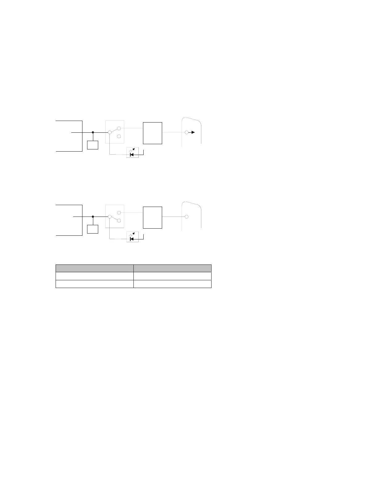
In the next drawing, SW1-2 is ON, which disconnects pin 6 from the RS232 transceiver.
The XPort™ Configurable Pin 1 (CP1) is configured for LED1.
XPort
6
CP1
JP4 - PIO
HEADER
4
MAX232
DB-9
P1
8CTS
RS232
LED1
IN1
OUT1
CTS
CP1 LED
SW1-2
PLD
OFF
ON
3.3v
When Configurable Pin 1 is configured for LED1, it will function as a status indicator for the
serial port.
Condition CP1 LED State
Idle Channel Solid on
Connected to network 4 Blinks every 4 seconds
CTS and RTS work together for hardware flow control. Configurable Pin 3 (CP3) should be
configured as RTS when Configurable Pin 1 (CP1) is configured as CTS. Select hardware
flow control as described in Flow on page 4-12.
See OEM Configurable Pins on page 6-13 for configuring CP1 as IN1 or OUT1.
XPort™ User Manual and Development Kit 2-5

 Loading...