Development Kit
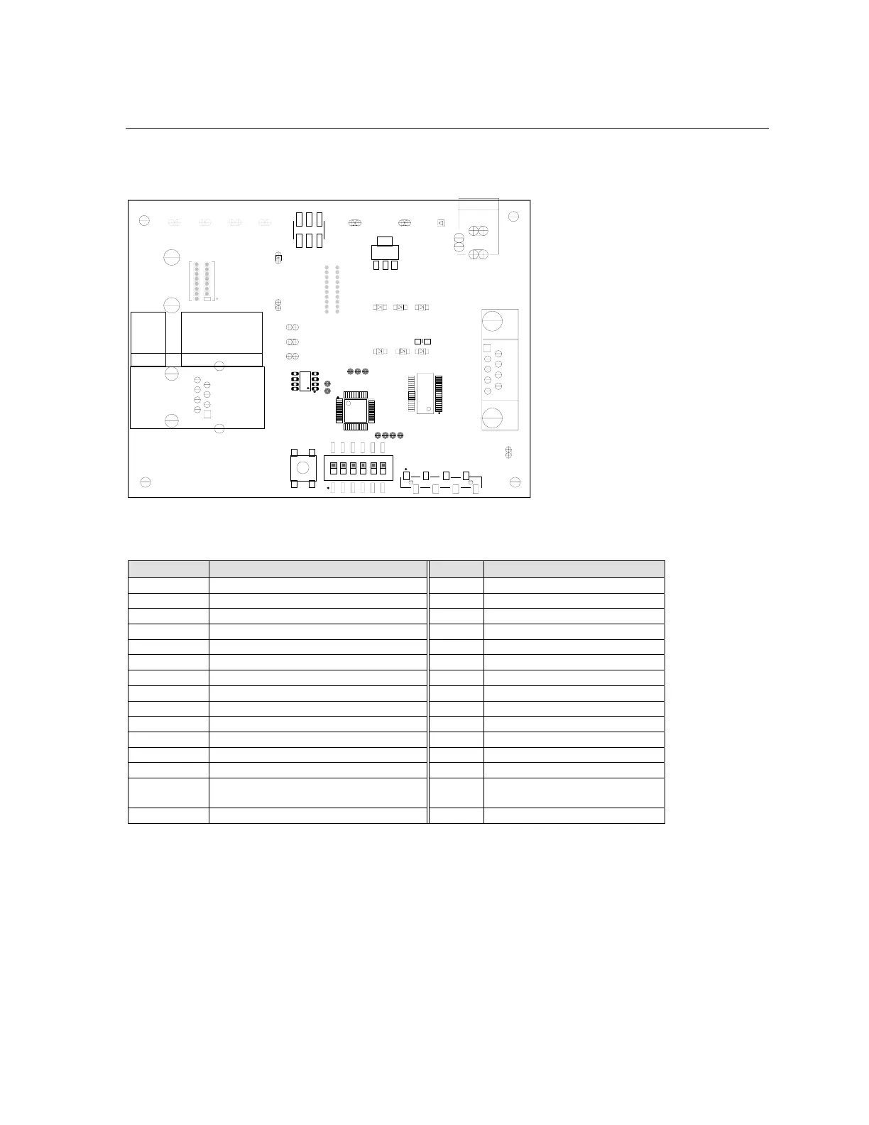
2.8 Board Layout
2.8.1 Component Identification
FP1
XPort Solder Pads
Select
Function
Selt Test
XPort Pin 6
to U2 CTS
XPort Pin 7
to U2 DCD
XPort Pin 8
to U2 DTR
XPort Pin 8
to U2 RTS
NO XPort
Pin 8 to U2
Loop-back
Self Test
SW
on
off
ON
1
OFF
2
OFF
3
OFF
4
ON
4
OFF
5
ON
6
XPort Socket
SC1
LANTRONIX XPORT TEST BOARD
TP1 TP2
TP3 TP4
TDI
TCK
TMS
TDO
Chassis
Ground
Chassis
Ground
TP6 TP5
JP4
TP12
Reset
TP11
TP13
TP8
3.3V
TP9
Signal Ground
Configurable Port Interface
JP5
U1
D4 D6
D5
RS232
RXD TXD
Valid Active Active
D7
D9
D8
CP1 CP2 CP3
PAD6
PAD7
PAD8
PLD
Control
PAD4
PAD3
U5
Slow
Timer
U4
SW2
SW1
PAD1
PAD2
PAD10
PAD9
Mode
16
RS232 Transceiver
U2
P1
1
RS232 to DTE Device
TP7
Chassis
Ground
D2
Reset
XPort
Power
5VDC In
J1
XPort D-Out
XPort D-In
JP3
R31
Chassis Ground
Table 8 - Component Identifier
Label Function Label Function
P1 RS232 Interface. DB-9F Connector TP1 NA
J1 +5VDC Input Connector TP2 NA
SC1 NA TP3 NA
SW1 Mode Switch TP4 NA
SW2 Reset Switch TP5 Chassis Ground
D2 XPort™ Power (Red) (LED) TP6 Chassis Ground
D4 RS232 Valid (Green) (LED) TP7 Chassis Ground
D5 RXD Active (Green) (LED) TP8 XPort™ 3.3VDC (3V3)
D6 TXD Active (Green) (LED) TP9 Signal Ground
D7 CP1- XPort™ pin 6 goes low (LED)
D8 CP2- XPort™ pin 7 goes low (LED) TP11 XPort™ Pin 5, Data In
D9 CP3- XPort™ pin 8 goes low (LED) TP12 XPort™ pin 3, Reset
JP3 Programming for PLD TP13 XPort™ Pin 4, Data Out
JP4 Configurable Pins Interface Header
Connector
FP1 XPort™ Solder Pads
JP5 Factory Test – NO connector
XPort™ User Manual and Development Kit 2-9

 Loading...