1
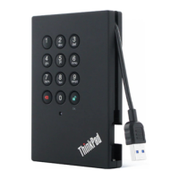
To cluster switches
2
To data network
switches
3
To management
network switches
Step
Perform on each controller Ports used
Cable the cluster interconnect ports to the cluster interconnect
switches.
• e0a
• e0b
Cable the UTA2 data ports to the data network switches.
• e0c and e0d
• or e0e and e0f
Cable the management ports to the management network
switches.
• e0M
DO NOT the plug power cords in at this point. Not applicable.
Step 2. To cable your storage, see “Cabling controllers to drive shelves” on page 22.
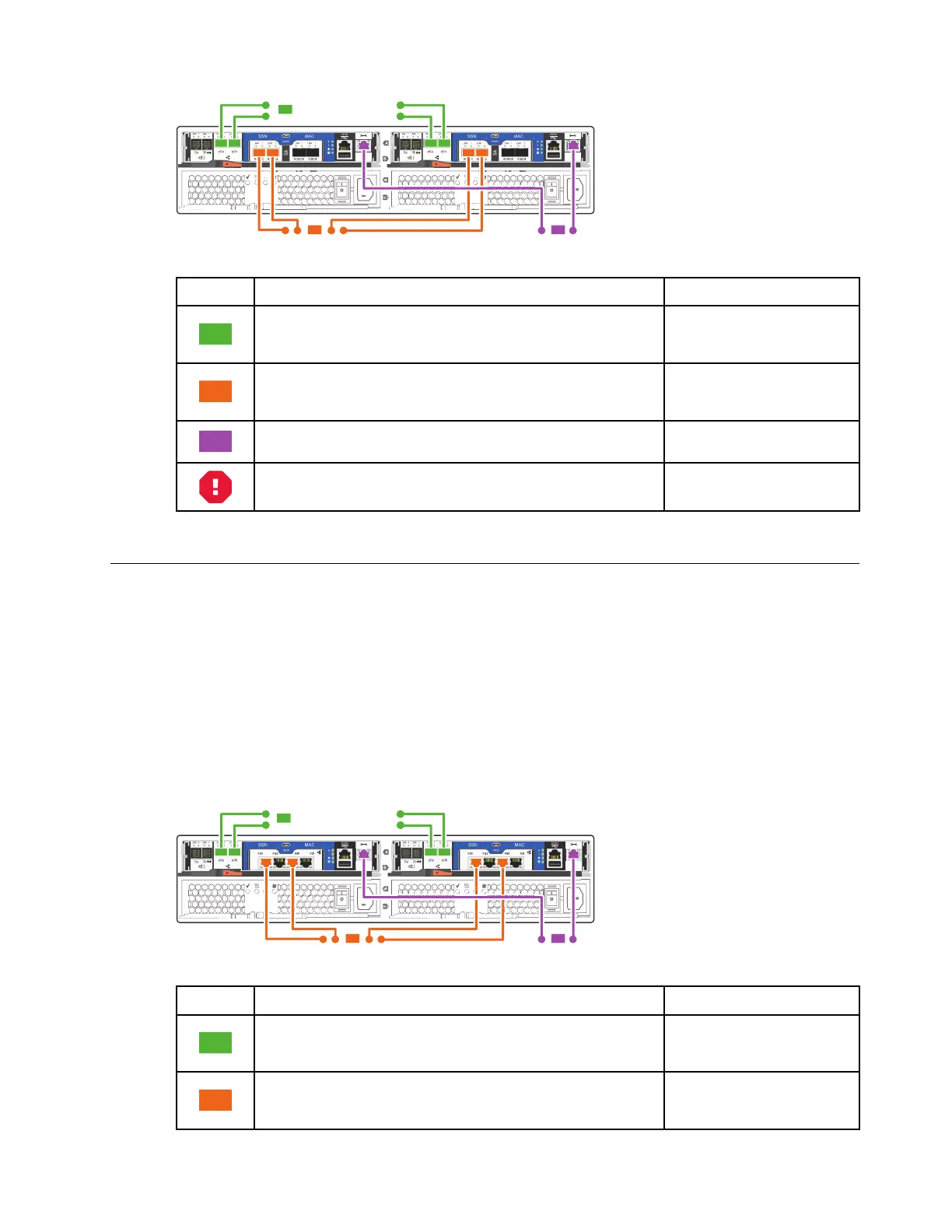
Cabling a switched cluster, Ethernet network configuration
Management network, Ethernet data network, and management ports on the controllers are connected to
switches. The cluster interconnect ports are cabled to the cluster interconnect switches.
Before you begin
See your network administrator for help connecting to the switches.
Step 1. Cable your system using the following steps:
Note: As you insert the connector, you should feel it click into place; if you do not feel it click,
remove it, turn it around and try again.
1
To cluster switches
2
To data network
switches
3
To management
network switches
Step
Perform on each controller Ports used
Cable the cluster interconnect ports to the cluster interconnect
switches.
• e0a
• e0b
Cable the UTA2 data ports to the data network switches.
• e0c and e0e
• or e0d and e0f
Chapter 4. System installation and setup 21
 Loading...