Front components overview
Diagnostics panel
The diagnostics panel is integrated in front I/O assembly on some models. For information about the controls
and status LEDs on the diagnostics panel, see Diagnostics panel.
Drive LEDs
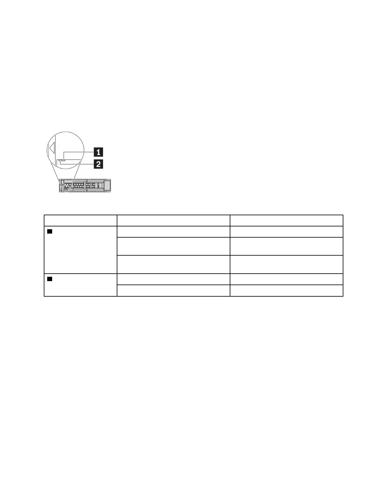
Each hot-swap drive comes with an activity LED and status LED and the signals are controlled by the
backplanes. Different colors and speeds indicate different activities or status of the drive. The following
illustration shows the LEDs on a Hard disk drive or solid–state drive.
Figure 4. Drive LEDs
Drive LED Status Description
1 Drive status LED (right) Solid yellow
The drive has an error.
Blinking yellow (blinking slowly, about one
flash per second)
The drive is being rebuilt.
Blinking yellow (blinking rapidly, about four
flashes per second)
The RAID adapter is locating the drive.
2 Drive activity LED (left) Solid green
The drive is powered but not active.
Blinking green The drive is active.
External diagnostics port
The connector is for connecting an external diagnostics handset. For more about its functions, see LCD
diagnostics panel/handset.
Hot-swap drives and drive bays
The drive bays on the front and rear of your server are designed for hot-swap drives. The number of the
installed drives in your server varies by model. When you install drives, follow the order of the drive bay
numbers.
The EMI integrity and cooling of the server are protected by having all drive bays occupied. Vacant drive
bays must be occupied by drive fillers.
LCD diagnostics panel assembly
The assembly comes with an integrated LCD diagnostics panel that can be used to quickly obtain system
status, firmware levels, network information, and health information about the system. For more about the
panel functions, see LCD diagnostics panel/handset.
Chapter 2. Server components 23

 Loading...


