Commissioning
Setting node address and baud rate
6
l
34
EDSMF2178IB EN 3.0
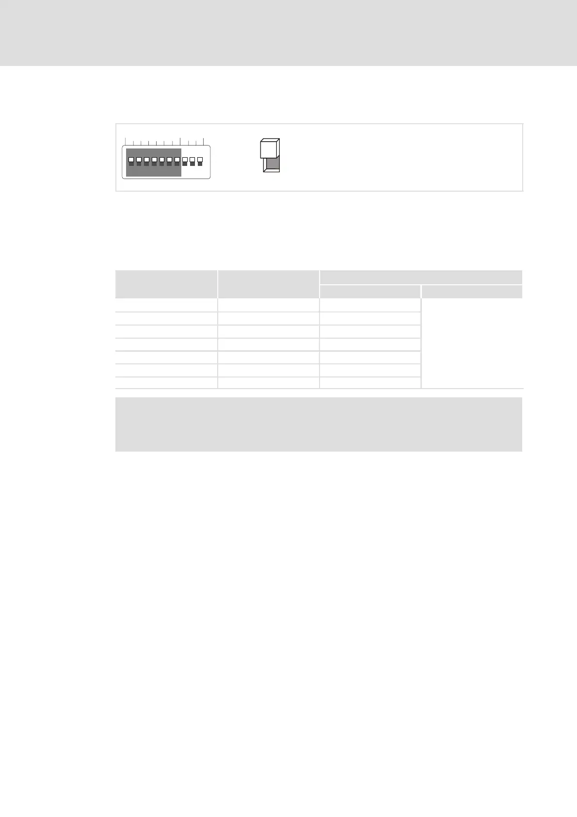
Node address setting
12345678910
OPEN
ON
OFF
BdAddress
Fig. 6−1 Address assignment via DIP switch
ƒ If several devices are connected to the CAN network, the node addresses must differ
from each other.
ƒ The desired node address results from the sum of the values of switches (1 ... 7) in
ON position.
Switch Value
Example
Switch position Node address
164OFF
16 + 4 + 2 + 1 = 23
2 32 OFF
3 16 ON
4 8 OFF
5 4 ON
6 2 ON
7 1 ON
) Note!
Switch off the voltage supply of the communication module, and then switch
it on again to activate the changed settings.
 Loading...