GA05141_0702 - 09/2004
36
Installation
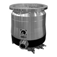
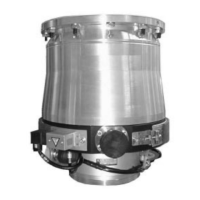
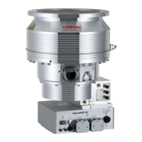
Fig. 22 Connection elements, installing the splinter guard and fixing the intake flange for the MAG (W) 1500 CT
Forevacuum flange
Purge gas
valve
Purge gas in
High-vacuum flange
DRIVE/BEARING
connection
TMS
connection
PK
connection
Heater band
Cooling water
connection
DN 200 CF
24 bolts M8 x 40
Installation torque per bolt 25
+5
Nm
Bolt quality: 10.9 according to
EN ISO 898-1 with coating
0,2% yield strength > 900 N/mm
2
MAG (W) 1500 CT
Correct
Wrong
Caution
Install the splinter guard as shown.
Installing the splinter guard upside
down may lead to contact between
splinter guard and rotor during fast
venting of the pump.

 Loading...