GA05141_0702 - 09/2004
82
Plug-in control
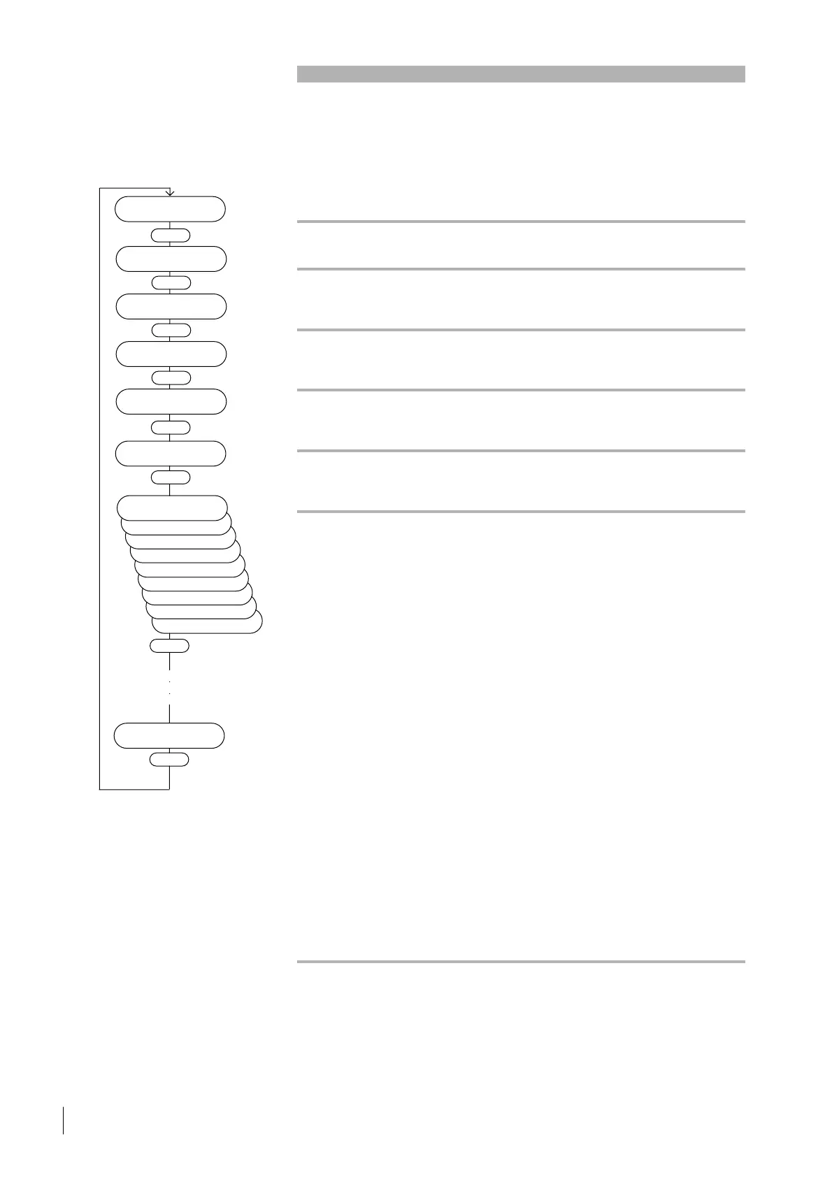
3.10.3 Menu Failure Storage
Menu item Description Adjustable value / option Ac-
cess
min. max. de- Unit
value value fault
Failure Total No. of total failures since actual value - r
65535 manufacturing date
Failure TMS No. of TMS-Failures since actual value - r
65535 manufacturing date
Refer to Failure TMS 1...4
(Section 6 “Troubleshooting”)
Failure Overload No. of Overload-Failures since actual value - r
65535 manufacturing date
Refer to Failure Overload
(Section 6 “Troubleshooting”)
Failure Temp.Bear. No. of bearing temperature failures actual value - r
65535 since manufacturing date
Refer to Failure Bearing Temp.
(Section 6 “Troubleshooting”)
Failure Mains No. of mains failures actual value - r
65535 since manufacturing date
Refer to Warning Mains Down
(Section 6 “Troubleshooting”)
F. Storage 0 10 In the event of a failure, the actual value - r
Bearing Temp. characteristic operating parameters
(failure information 0...8) will be
saved in the memory chip using a
ring arrangement capable of saving
20 failure events (0...19) in chrono-
logical order. Index 0 represents
the most recent, and index 19 the
oldest failure event. Operating the
Up/Down keys lets you step through
the index range 0...19. Operating the
Enter key lets you step through the
failure information (0...8) indicating
the following:
Failure information 0:
Failure message (in plain text)
Failure information 1:
Date and time of the failure which
has occured
Failure information 2:
Number of operating hours for the
pump
Failure information 3:
Actual frequency during operation
Failure information 4...8:
Extended parameter numbers. The
1st number represents the para-
meter number, the 2nd number
represents the parameter value.
For more information about
parameter numbers see Table B
“Parameters for the analog output”
P11: 46
P7: 73
P127: 0
Enter
Failure Total
65535
Enter
Failure TMS
65535
Enter
Failure Overload
65535
Enter
Fail. Temp.Bear.
65535
Failure Mains
65535
Enter
Failure Storage
Enter
P123: 0
P125: 0
300 Hz
167772.16 h
99.12.31 00:00
F. Storage 0 10
Bearing Temp.
Enter
●
●
●
F. Storage 8 10
Bearing Temp.
Enter

 Loading...