LightLas 532 – Operator's Manual Rev. No 01 Page 35 of 115
1. Emergency Stop Switch
This switch is provided a fast response shutdown of the laser system in the event
of some serious problem occurring. It is a RED color push switch that locks
down when pushed and in, all internal power will be removed. In order for
system to restore the power, the button switch must be twisted and released it.
2. Key Switch
This key switch is the main power ON/OFF switch. The power can only be turned
on by inserting the key and rotating clockwise to the ON position. In the ON
position the key cannot be removed. The key should be stored in a safe and
controlled place.
3. Laser Aperture
The Laser Delivery Unit’s fiber is connected here. The fiber connector must be
fully screwed in since there is an interlock switch which must engaged in order
for the Laser to function. No laser beam can be delivered through unless the
fiber is securely attached.
4. Delivery Key Connector
Each Delivery Unit has its own type of “Delivery Key” connector that must be
fitted to this socket so the microprocessor can recognize it. Always make sure
the correct Delivery Key is inserted for the LDU that is being used.
5. LIO Illumination Control
When the LIO is connected to the LightLas 532 Laser Console, this control knob
can be used to adjust the intensity of the Illumination lamp.
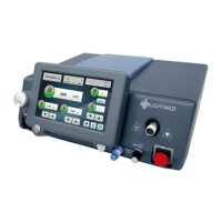
6. LCD Control Panel
This LCD Control Panel locates in front of the Laser Console and can easily be
removed by the operator and placed close to the site of the laser treatment in
order to maintain good control over the laser settings and displays. A cable
connects the LCD Control panel to the Laser Console and it is coiled up under the
hinged top cover of the Laser Console. This is a touch panel control and
software system embedded it. All controls are shown on the LCD panel including
Duration, Interval, Aiming intensity, Output power, SP Mode selection, and Shot
counter.
7. LIO Power
This connector is used to provide the power source the LIO Illumination.