3. Product Overview HDMI-3D-OPT series – User's Manual 21
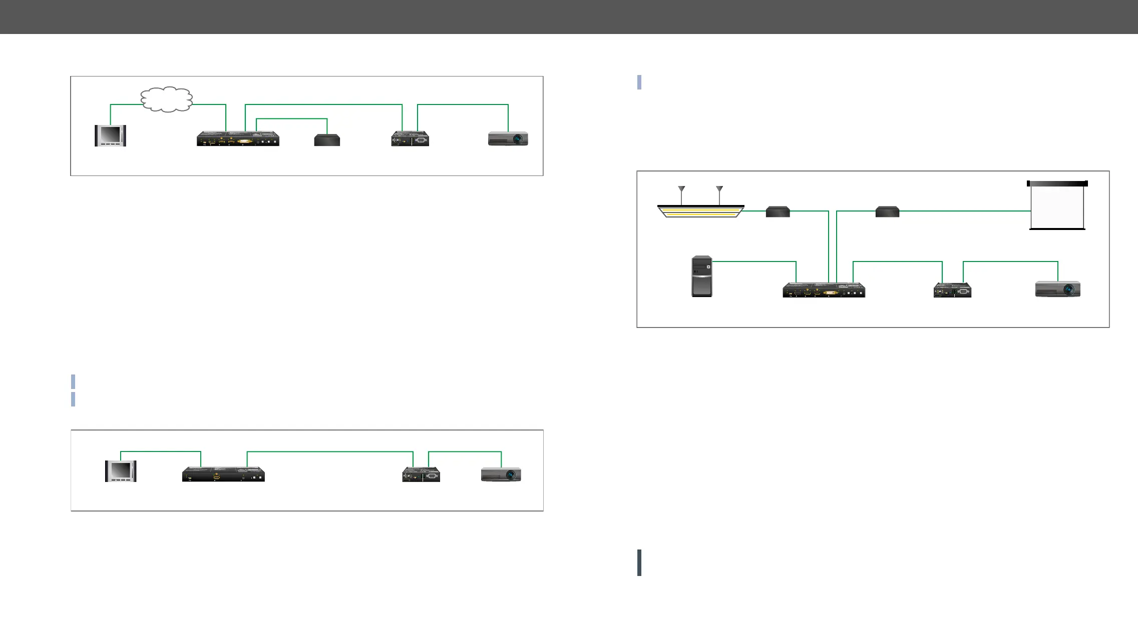
RS-232 Signal Transmission - Example 1
The following ways are available for controlling the devices:
▪ The System controller can communicate with the Transmitter
the local IP:port address.
▪ The System controller can communicate directly with the Projector or an Extender via their IP:port address.
▪ The System controller can communicate directly with the RS-232 Relay box connected to the Transmitter.
In this case, Command Injection mode has to be enabled on the local RS-232 port.
▪ The Transmitter can send a command (e.g. as an action by the Event Manager) to the IP:port address
of the Projector or the Receiver
Command Sending
▪ 192.168.0.100:6107 port to control the transmitter.
▪ 192.168.0.100:10001 port to control the transmitter.
▪ You can send commands to the 192.168.0.100:8001 port to control the projector. This port number
means the RS-232 interface of the optical output port (O1).
INFO: Above values are examples and based on factory default settings.
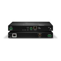
RS-232 Signal Transmission - Example 2
The Concept
You can control the Projector over the extenders with the System controller. The controller is connected to
the local RS-232 port of the Transmitter which transmits the signal toward the Receiver
line. The Projector is connected to the local RS-232 port of the Receiver. The serial connection is bidirectional
which means the controller gets back the responses of the projector.
In this case the RS-232 port of the transmitter and receiver either has to be set to Pass-through mode.
System controller
LAN FIBER OPTICAL RS-232
SW4-OPT-TX240RAK
transmitter
HDMI-3D-OPT-RX150RA
receiver
Projector
Ethernet
LAN
Relay box
RS-232
POWER
HDCP
RS-232
FUNC.
USB
CONT.
HDMI
SIGNAL
LASER
HOTPLUG
EMULATE
USB LINK
FIBER LINK
:
:
1 4
5
3
2
USB
Autoselect
SHOW
ME
AUDIO
SELECT
VIDEO
SELECT
VIDEO VIDEO VIDEOAUDIO AUDIO AUDIO VIDEO
AUDIO
HDCP AUDIO1
DP IN DVI-D IN
RST
AUDIO2
AUDIO1 IN
HDMI2 INHDMI1 IN
System controller
RS-232 FIBER OPTICAL RS-232
HDMI-3D-OPT-TX210RAK
transmitter
HDMI-3D-OPT-RX150RA
receiver
Projector
POWER
HDCP
RS-232
FUNC.
USB
CONT.
HDMI
SIGNAL
LASER
HOTPLUG
EMULATE
USB LINK
FIBER LINK
2
1
USB
SHOW
ME
AUDIO
SELECT
VIDEO AUDIOHDCP AUDIO1
RST
AUDIO2
AUDIO1 IN
HDMI IN
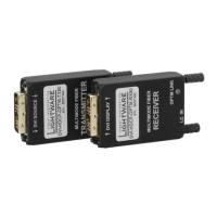
GPIO Interface
GPIO Options - Example
The Concept
Ceiling lamp is turned off by Relay 1 and projection screen is rolled down by Relay 2 when signal received
Settings of the Transmitter
▪ For Relay 1: create an event in Event Manager: when signal is present on Input 1 (I1) then set GPIO pins
to low level for Relay 1 opening. Also create another event when signal is not present on Input 1 (I1)
then set GPIO pins to high level for Relay 1 closing.
▪ For Relay 2: create an event in Event Manager when signal is present on Input 1 (I1) then set GPIO pins
to high level for Relay 2 closing. Also create another event when signal is not present on Input 1 (I1)
then set GPIO pins to low level for Relay 2 opening.
send signal to Relay 1 to open which results turning off the lights. Furthermore GPIO pins also send signal
signal to Relay 2 to open so projection screen returns to its enclosure.
ATTENTION! Please always check the electrical parameters of the devices what you want to control. The
maximum current of one GPIO pin is 30 mA, the maximum total current for the seven pins is 180 mA.
See the LDC settings for GPIO port in the GPIO section. See also the details about the Event Manager settings
in the Event Manager section.
PC Projector
HDMI OUT
GPIO
SW4-OPT-TX240RAK
transmitter
Projection
screen
GPIO
Ceiling lamp
DVI-D IN
Relay 1 Relay 2
POWER
HDCP
RS-232
FUNC.
USB
CONT.
HDMI
SIGNAL
LASER
HOTPLUG
EMULATE
USB LINK
FIBER LINK
HDMI-3D-OPT-RX150RA
receiver
FIBER OPTICAL
:
:
1 4
5
3
2
USB
Autoselect
SHOW
ME
AUDIO
SELECT
VIDEO
SELECT
VIDEO VIDEO VIDEOAUDIO AUDIO AUDIO VIDEO
AUDIO
HDCP AUDIO1
DP IN DVI-D IN
RST
AUDIO2
AUDIO1 IN
HDMI2 INHDMI1 IN