HDMI-3D-OPT series – User's Manual 28
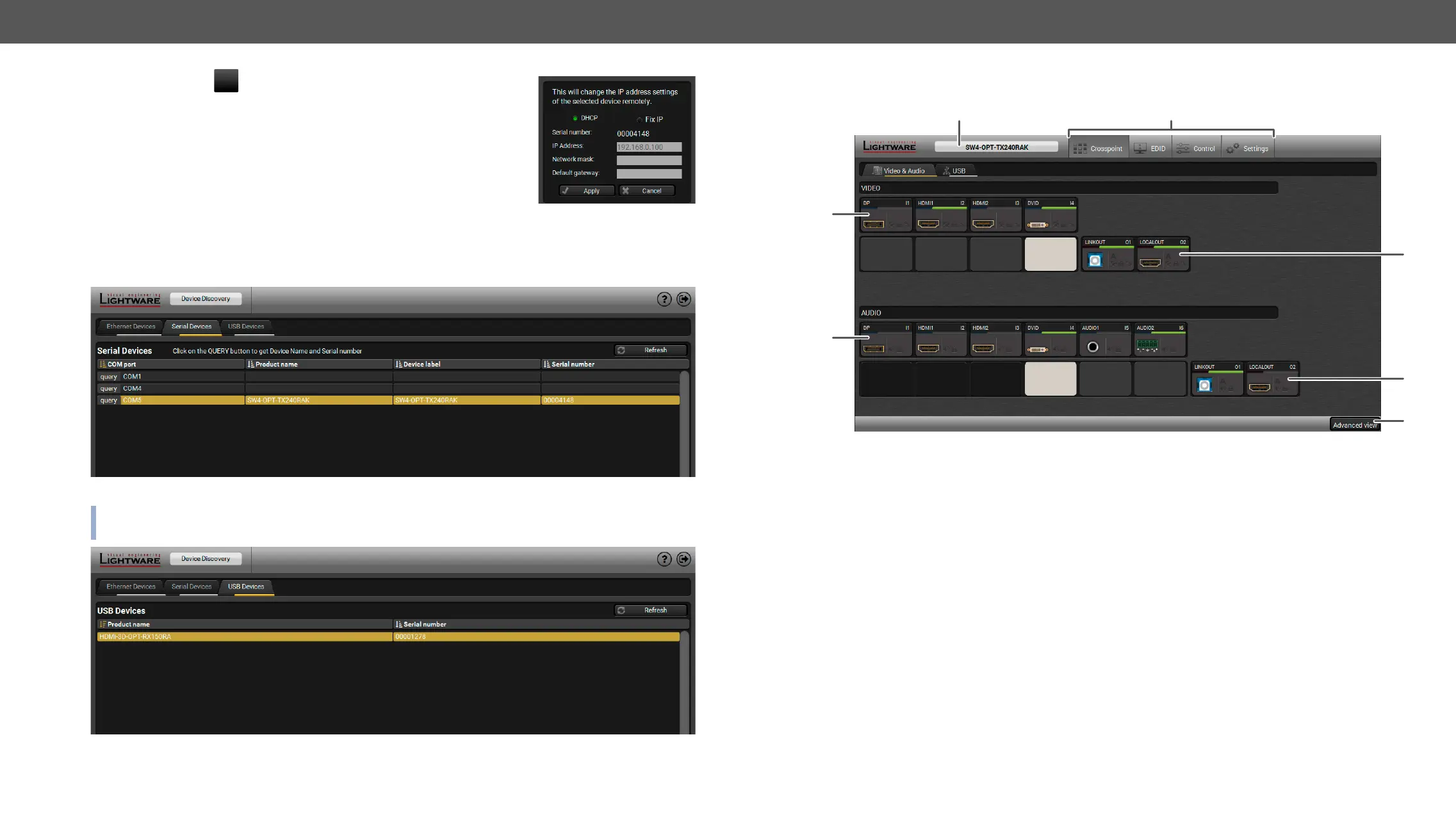
Change IP Address
To modify IP address settings quickly it is not necessary to enter the device's
the IP address.
You can see the new settings only in this window.
Step 3. Select the unit from the discovered Ethernet devices or under Serial devices; when the device is
connected through RS-232 click on the Query button next to the desired serial port to display the
device’s name and serial number. Double click on the transmitter or select the device and click on the
Connect button.
Serial devices tab in LDC
ATTENTION! Before the device is connected via the local RS-232 port, make sure that Control mode and
LW3 protocol are set on the serial port.
USB tab in LDC
1
Main menu The available menu items are displayed. The active one is showed with
dark grey background color.
2
Information ribbon The label shows the device label which can be edited in the
Settings menu - Status tab. Device discovery window can be displayed by
clicking on this ribbon.
3
Video input ports Each tile represents a video input port. The tile below the port shows the
current crosspoint setting; if the port is switched to the output, the color of
the tile is white, otherwise grey.
4
Audio input ports Each tile represents an audio input port. The tile below the port shows
current crosspoint setting; if the port is switched to the output, the color
of the tile is white, otherwise grey. Dark grey means the audio port is not
allowed to embed in the current video input port.
5
Advanced view Displaying the , showing the Terminal window and
6
Audio output ports The audio output of the optical link and local HDMI out ports. Clicking on
the tile opens the Digital Audio Outputs port properties window.
7
Video output ports The video output of the optical link and local HDMI out ports. Clicking on
the tile opens the port properties window.
2
3
4
5
6
7
1