[DVR316]
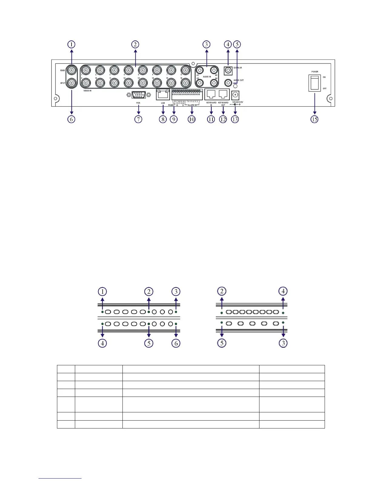
1. Main monitor 9. RS-485
2. Camera inputs For PTZ connection
Analog camera BNC inputs 10. Alarm I/Os
3. Audio inputs Alarm input switches, 1 N/O alarm output,
Four RCA audio connectors and 1 N/C alarm output
4. External IR receiver (RCA) 11. RJ-45 Keyboard-in
5. Audio output Connected from previous DVR’s
6. Spot monitor keyboard output in daisy chain.
a. Spot monitor accessible by keyboard. 12. RJ-45 Keyboard-out
b. Each spot output can be Connect to the next DVR’s input.
programmable for alarmed camera RJ-45 connector
display and sequence display. 13. DC 12V input
7. VGA output 15. Power switch
8. Network RJ-45 connector
Chapter 1-3. System LED Status Panel
System LEDs are meaningful while operating the DVR. The status of each LED is described
as in the following table:
Item
LED Description Color
1 BACKUP Backup LED indicator Green (blinking)
2 POWER DVR power on/off indicator Yellow
3 HDD Master HDD recording indicator Green (blinking)
4 ALARM External alarm switches indicators when
motioned or alarmed
Red
5 REC Recording indicator Yellow
6 NET Network indicator Green
[DVR308/316]