Page 12 of 76
Electrical installation:
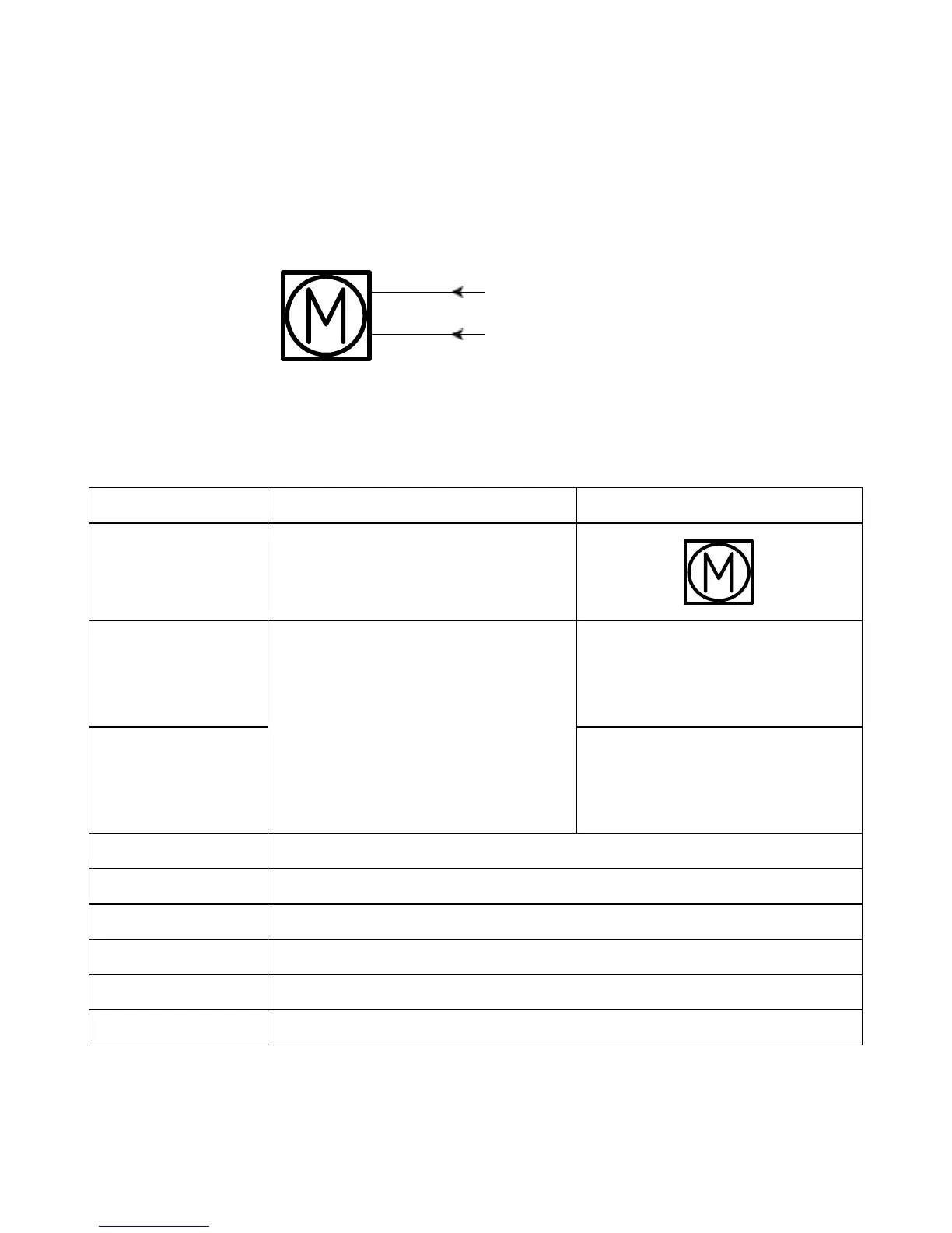
Actuator without feedback:
BROWN
BLUE
Connection diagram:
Fig. 1 : 36xxxxx00/10xxxxxx
36xxxxxxx000xx-xxxxxxxxxxxxxxx
Input/Output Specification Comments
Description Permanent magnetic DC motor.
See connection diagram,
fig. 1 above
Brown 12, 24 or 36VDC (+/-)
12V ± 20%
24V ± 10%
36V ± 10%
Under normal conditions:
12V, max. 26A depending on load
24V, max. 13A depending on load
36V, max. 10A depending on load
To extend actuator:
Connect Brown to positive
To retract actuator:
Connect Brown to negative
Blue To extend actuator:
Connect Blue to negative
To retract actuator:
Connect Blue to positive
Red Not to be connected
Black Not to be connected
Green Not to be connected
Yellow Not to be connected
Violet Not to be connected
White Not to be connected
I/O specifications: