Page 9 of 76
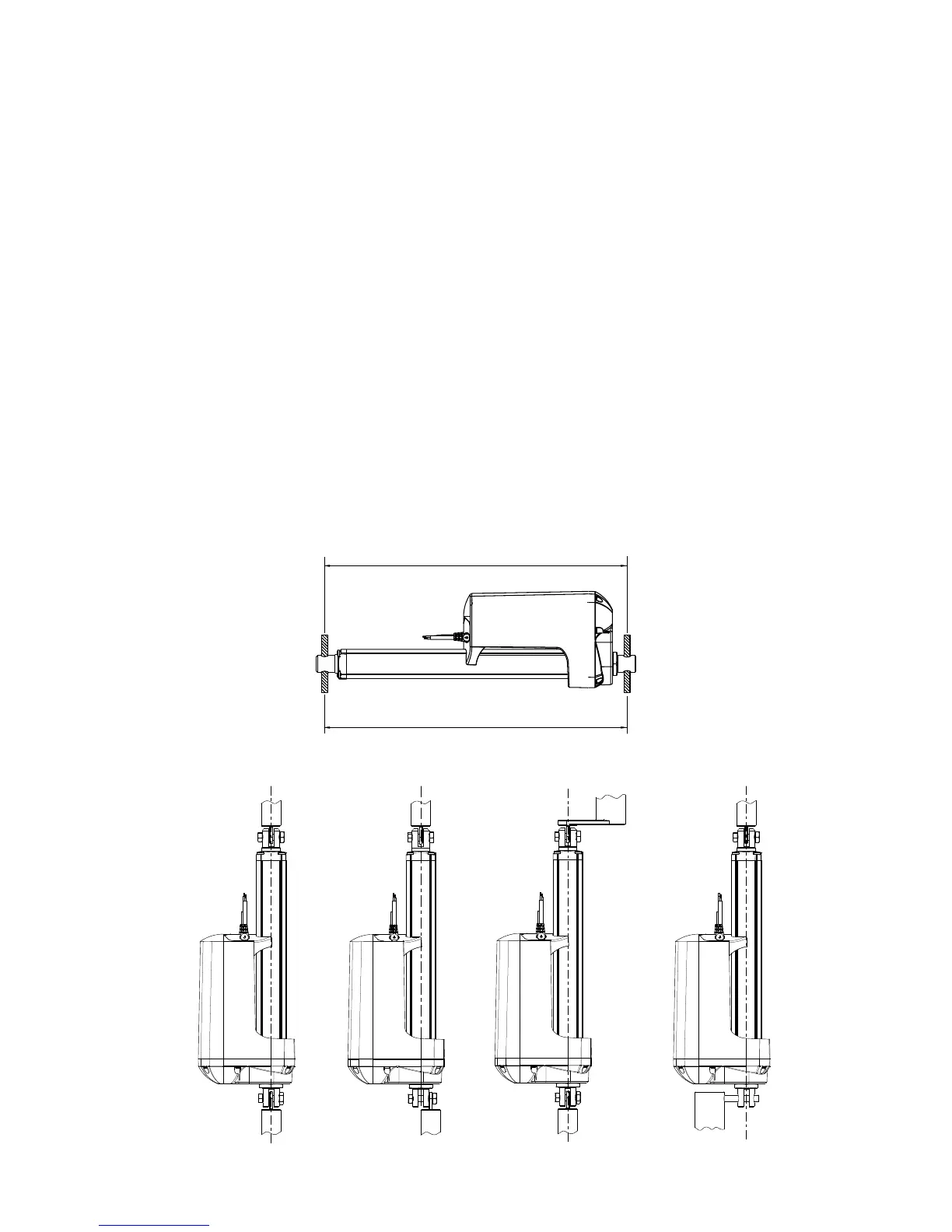
Mounting guidelines
LINAK
®
linear actuators are quickly and easily mounted by slipping pins through the holes on each
end of the units and into brackets on the machine frame and the load.
The mounting pins must be parallel to each other as shown in Figure 1. Pins, which are not parallel
to each other, may cause the actuator to bend and be damaged.
The load should act along the stroke axis of the actuator since off centre loads may cause bending
and lead to premature failure. See Figure 2.
Make sure the mounting pins are supported in both ends. Failure to do so could shorten the life of
the actuator. Also, avoid applying a skew load on the actuator.
The actuator can rotate around the pivot point in the front and rear end. If this is the case it is of
high importance that the actuator is able to move freely over the full stroke length, both during
the development and during daily operation. Please pay special attention to the area around the
housing where parts can be trapped and cause damages to the application and actuator.
In applications with high dynamic forces LINAK recommends not to use the fully extended or
retracted position over longer time, as this can damage the endstop system permanently.