Page 33 of 76
Actuator with endstop signals and absolute positioning - PWM:
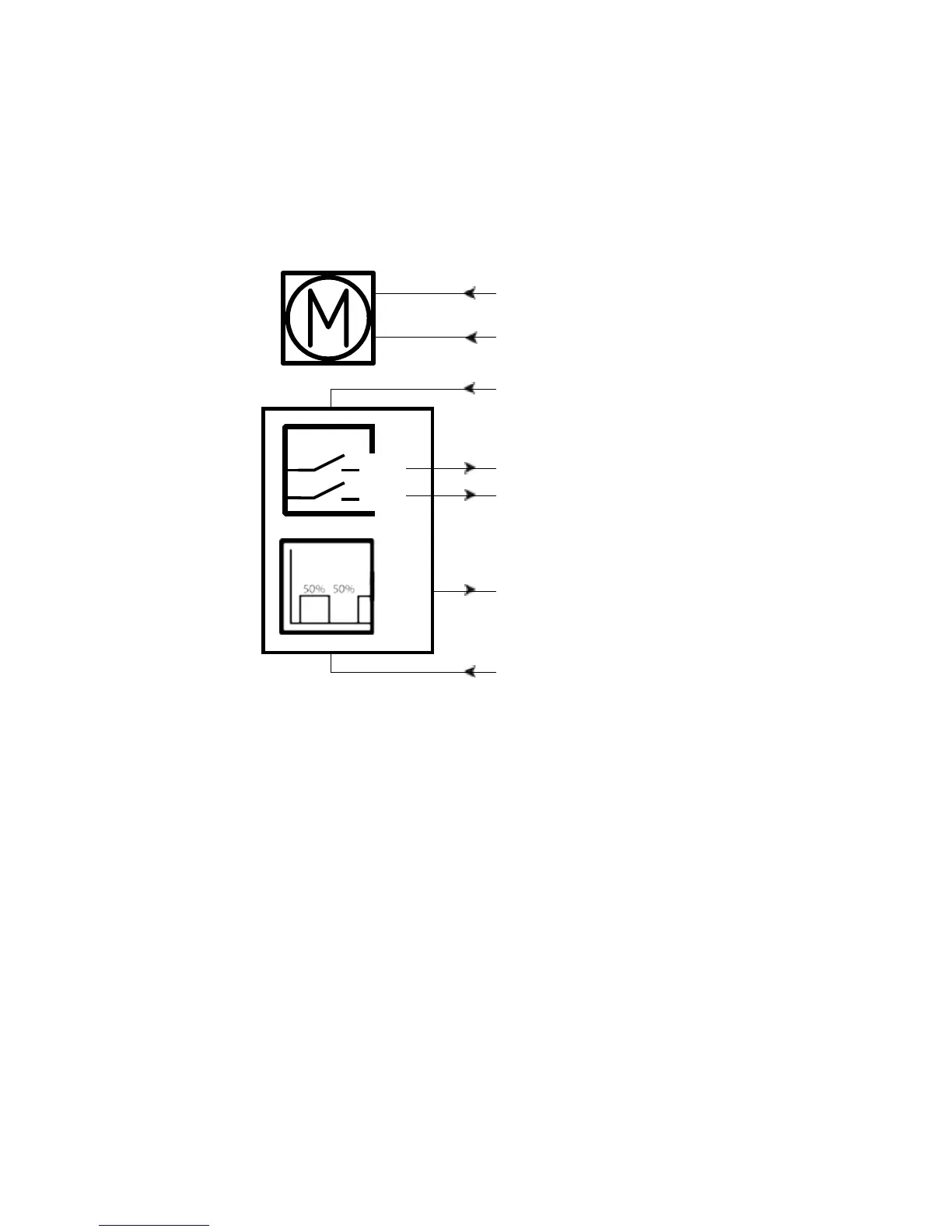
Connection diagram:
Fig. 12 : 36xxxxx25/26xxxxxx
36xxxxxxxF00xx-xxxxxxxxxxxxxxx
BROWN
BLUE
PWM
YELLOW*
GREEN*
IN
OUT
RED
VIOLET
+
BLACK
-
*YELLOW/GREEN:
Endstop signals out are NOT potential free!
If you wish to use the endstop signals, you will have to keep power on the brown, blue, red and
black wires, otherwise the signal will be lost.