Page 43 of 76
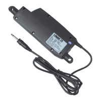
Actuator with IC Advanced - with BusLink:
I/O specifications:
Input/Output Specification Comments
Description Easy to use interface with integrated
power electronics (H-bridge).
The actuator can also be equipped
with electronic circuit that gives an
absolute or relative feedback signal.
IC Advanced provides a wide range
of possibilities for customisation.
The version with “IC option” cannot
be operated with PWM (power
supply).
See connection diagram,
fig. 16, page 42
Brown 12-24VDC + (VCC)
Connect Brown to positive
12V ± 20%
24V ± 10%
12V, current limit 25A
24V, current limit 13A
Note: Do not change the power
supply polarity on the brown and
blue wires!
Power supply GND (-) is electrically
connected to the housing
Current limit levels can be
adjusted through BusLink
If the temperature drops below
0°C, all current limits will auto-
matically increase to 30A
Blue 12-24VDC - (GND)
Connect Blue to negative
12V ± 20%
24V ± 10%
12V, current limit 25A
24V, current limit 13A
Red Extends the actuator On/off voltages:
> 67% of V
IN
= ON
< 33% of V
IN
= OFF
Input current: 10mA
Black Retracts the actuator
Green Endstop signal out Output voltage min. V
IN
- 2V
Source current max. 100mA
Endstop signals are NOT poten-
tial free. Endstop signals can be
configured with BusLink software
according to any position needed.
Only use one virtual endstop -
keep one end open for initialisa-
tion. (See I/O specifications for
endstop on page 14).
Yellow Endstop signal in
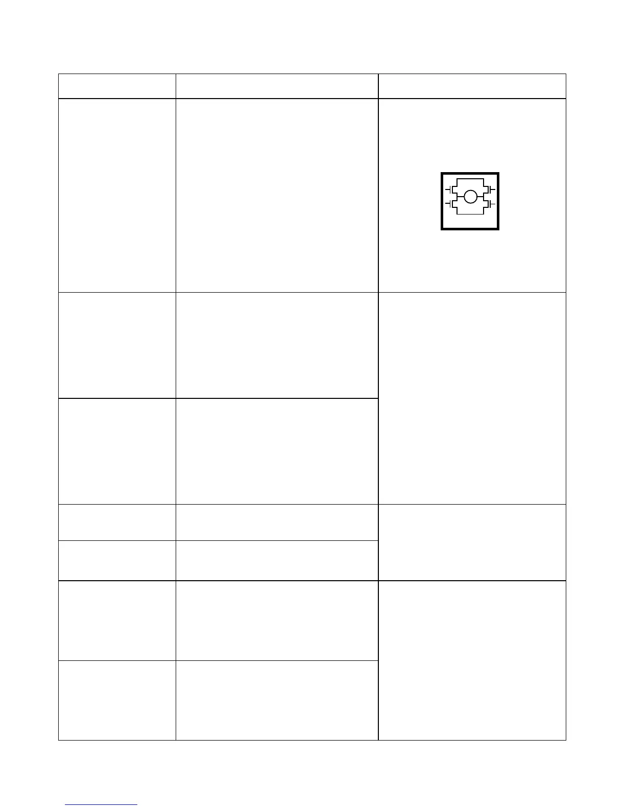
M
H-Bridge