LinMot
System Overview
User Manual V1.01 3-5
3.6 Driving and operating modes of LinMot
®
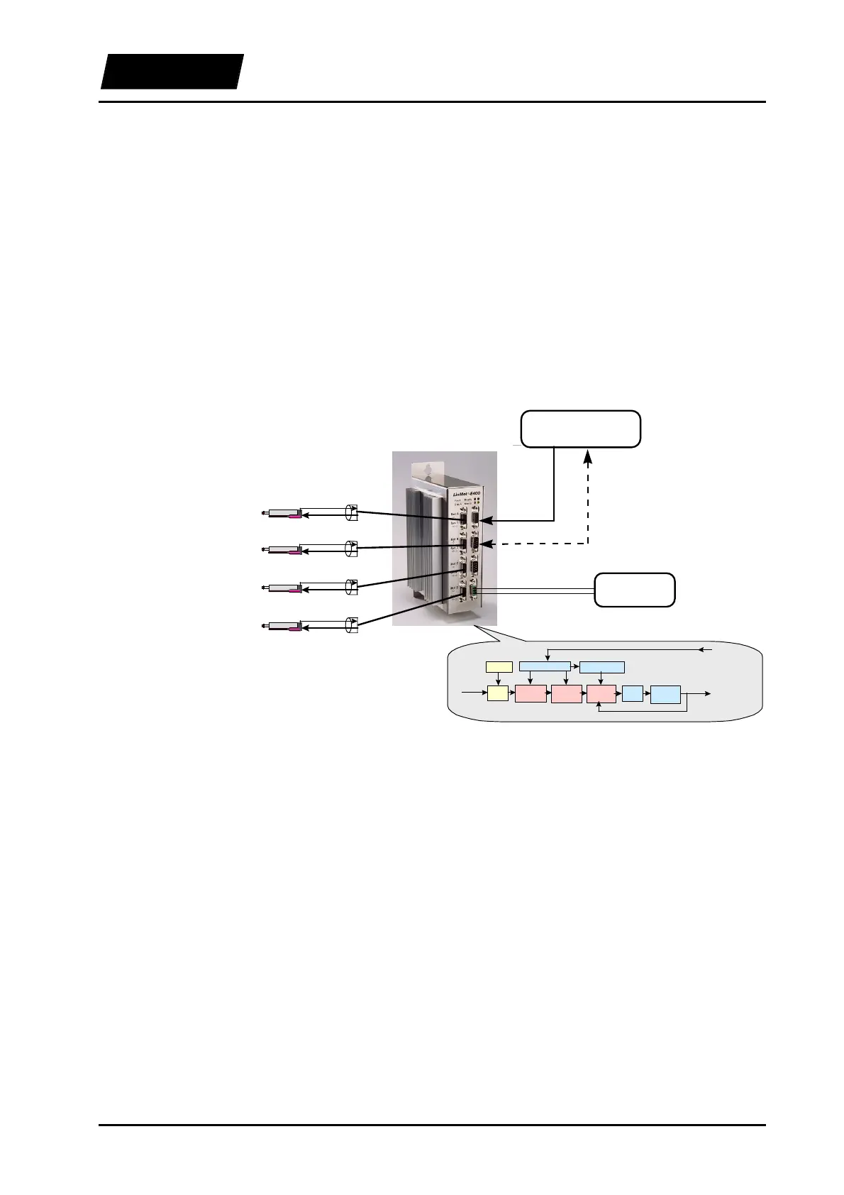
3.6.1 Driving concept
The basic idea of LinMot
®
P consists in having the control tasks executed as peripheral
as possible in order to free the higher-level control systems from unnecessary and
calculation-intensive ballast. The system configuration is therefore accordingly simple,
as the higher-level control system just outputs the actual target value and monitors some
feedback information. The following sections will implicitly refer to LinMot
®
P linear
motors as actuators when no specific indication is provided. In this case the target value
consists in the position set value to which the drives should move, while the feedback
information typically represents a following error message. In the case of stepper motors
and electromagnets these statements can be interpreted by analogy.
DC supply
PLC / PC / VME
System
Error message
Power circuitr
su
l
Si
nal circuitr
su
l
Ref. position
Power
Power
Position/Tem
.
Power
Position/Tem
.
Power
Filter
Position-
Control
Current-
Control
Velocit
-
Control
Commutation
Sensor Processin
Power-
Am
l.
PW
Curves
Reference
Position
Position
Tem
eratur
Power
Position/Tem
.
Position/Tem
.
Figure 3-3: LinMot
®
’s peripheral position control frees the higher-level control
system from calculation intensive tasks.
3.6.2 Operation modes
Different modes of operation are available to the user. These allow optimal embedding
of the actuators in the control concept of the machine and the respective application. The
LinMot
®
AT software currently supports the following modes of operation:
• direct digital reference value setting
• setting two target values depending on a high/low signal
• executing two predefined curves based on a trigger signal
• continuous operation, e.g. periodical execution of a curve
In all these modes a filter can be connected in order to limit the derived signals like for
example the speed or acceleration. The following table shows typical application
examples for the different modes of operation.