LinMot
Design and Installation
User Manual V1.01 4-14
4.5 Signal interfaces
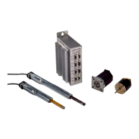
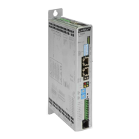
The signal interfaces of the electronic unit families E100/E200/E400 and
E1000/E2000/E4000 are identical and are described together in this chapter.
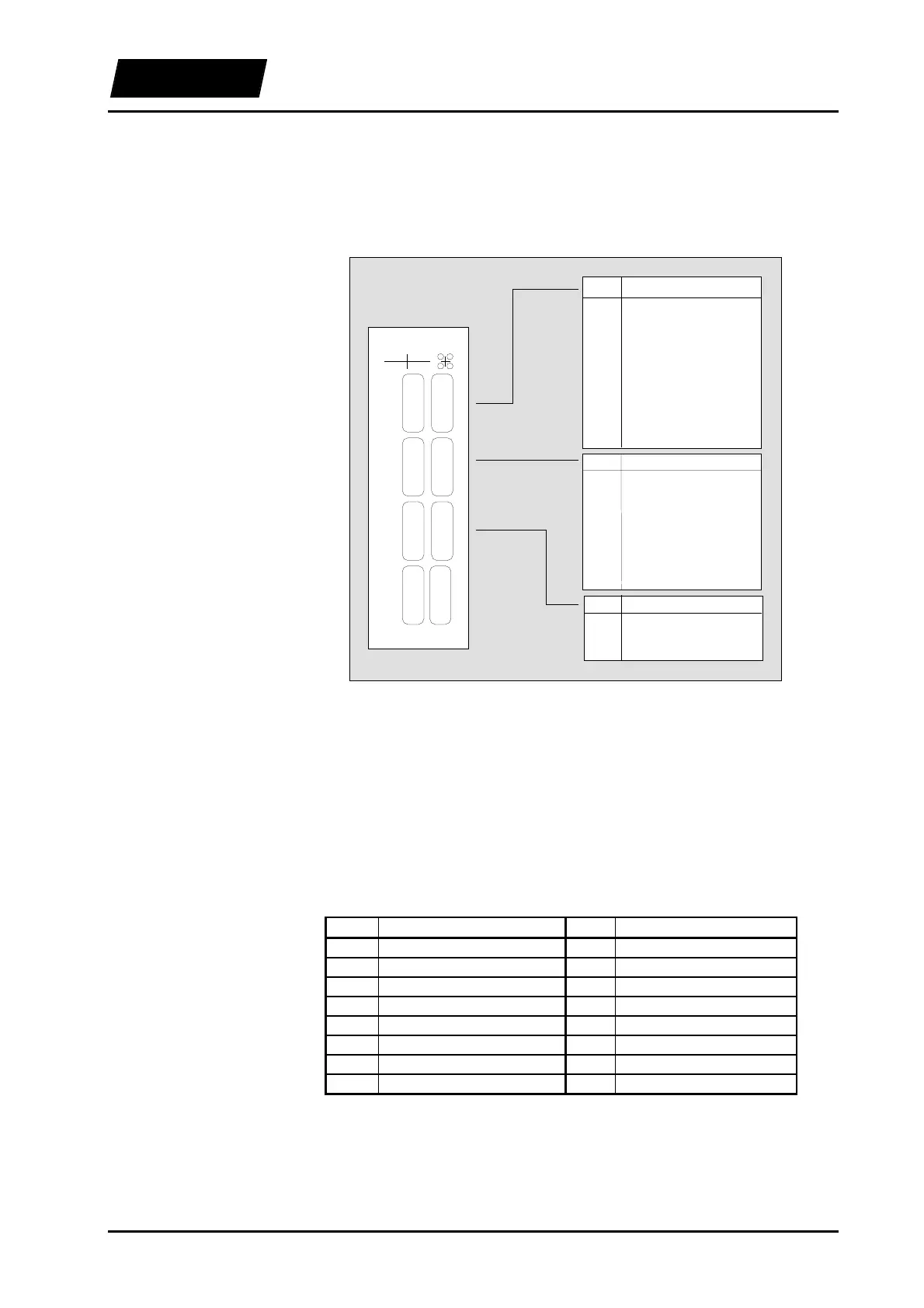
LinMot
-E400
Sys 2
Mot B
Sys 1
Mot A
Com
Mot C
PWR
Mot D
Ready
Stat B
Fault
Stat A
Pin
1
2
3
5
6
7
11
12
13
14
15
Sys 1
STOP -
STOP+
FREEZE+
+5V
RELAIS IN
FREEZE -
POSITION ERRROR OUT
RELAIS CLOSER
ERROR OUT
WARNING OUT
GND
Pin
1
2
3
4
5
6
7
8
9
Sys 2
TRIG/ANALOG IN 1
TRIG/ANALOG IN 2
RUN+
INIT+
GND
TRIG/ANALOG IN 3
TRIG/ANALOG IN 4
RUN -
INIT -
Pin
2
3
5
Com
RS-232 TX
RS-232 RX
GND
Figure 4-12: Signal interfaces
The interfaces are accessible from the front of the unit through three D-Sub connectors
SYS1, SYS2 and COM.
4.5.1 SYS1 interface
The operating states FREEZE and STOP of the electronic unit are driven through the
inputs of the SYS1 interface. The outputs WARNING OUT, ERROR OUT and
POSITION ERROR OUT carry internal warnings and error messages to the higher-level
control system. Further, a message output MSG for internal state output is available.
Table 4-1: Pin configuration of the SYS1 connector
Pin Description Pin Description
1 STOP - 9 Do not connect
2 STOP + 10 Do not connect
3 FREEZE + 11 POSITION ERROR OUT
4 Do not connect 12 MSG
5 +5V 13 ERROR OUT
6 Do not connect 14 WARNING OUT
7 FREEZE - 15 GND
8 Do not connect