LinMot
System Overview
User Manual V1.01 3-8
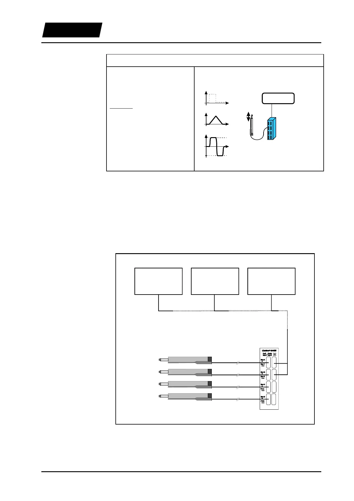
7. Example: Movement with constant speed
A constant, linear movement
should be triggered by means of a
simple digital signal.
Solution:
operating mode: ‘Two Position’
with filter. Set the end positions
to the boundaries of the stroke
range and the v
max
parameter to
the desired maximum speed.
Hint: The movement can be
stopped at any time with the
FREEZE signal.
t
‘digital out’
high
low
t
s
smax
smin
v
vmax
t
-vmax
LinMot
E
LinMot
P
s
PC / PLC
mode:
‘two position’
‘digital out’
3.6.3 Connection to higher-level control systems
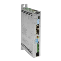
The electronic units LinMot
®
E can be controlled by higher-level control systems
directly by means of analog or digital input/output signal lines. The necessary
parameterisation is done with the LinMot
®
Talk software via an RS-232 connection.
Networking via CAN-bus or RS-232 is also possible on specific customer request.
PLC System
Analog / Digital IO's
VME System
Analog / Digital IO's
PC
Extension Card
Analog / Digital IO's
up to 10m
up to 10m
up to 10m
up to 10m
Figure 3-4: Connecting LinMot
®
to an higher-level control system