LinMot
System Overview
User Manual V1.01 3-7
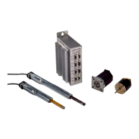
4. Example: Digital selection between two reference curves
Following a trigger signal from a
PLC, the motor moves between
two given position following
predefined trajectories.
Solution:
Operating mode: ‘Trigger Curve’.
Acceleration limiter and speed
limiter set to the desired maximal
values.
‘trigger out’
t
high
low
LinMot
E
LinMot
P
s
PC / PLC
mode:
‘two position’
‘trigger out’
s
t
v
vmax
t
-vmax
a
amax
t
-amax
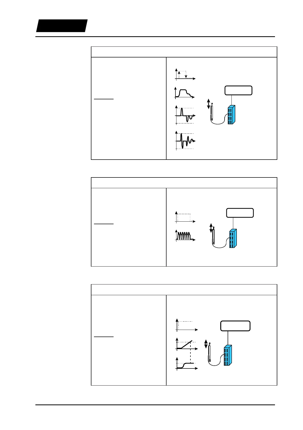
5. Example: Periodical movement sequence
The motor executes a previously
defined curve cyclically with a
given frequency.
Solution:
Operating mode: ‘Continuous
Curve’.
Acceleration limiter and speed
limiter set to the desired maximal
values.
‘digital out’
t
high
low
s
t
LinMot
E
LinMot
P
s
PC / PLC
mode:
‘continuous’
‘digital out’
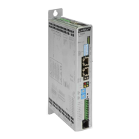
6. Example: Synchronization on a speed value
A linear movement should be
executed from a particular point
and with a previously defined
speed.
Solution:
Operating mode: ‘Analog’,’Two
Position’ or ‘Trigger Curve’.
The reference position should be
set in such a way, that the speed
limiter will be active in the
synchronization range.
t
s
ssync
t
v
vsync
LinMot
E
LinMot
P
s
PC / PLC
mode:
‘continuous’,
‘two position’
or
‘curve’
‘digital out’
‘digital out’
t
high
low