LinMot
Design and Installation
User Manual V1.01 4-18
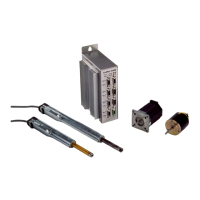
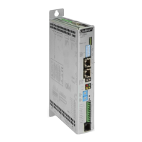
4.6 Actuator interfaces
The interfaces for the connection of the actuators are found on the front of the electronic
unit and are named Mot A, Mot B, Mot C and Mot D.
Caution: The pin configuration for the actuators of the two electronic unit series
E100/E200/E400 and E1000/E2000/E4000 are not identical. The incorrect connection
of an actuator can lead to damage of the electronic unit and of the actuator itself.
4.6.1 Connection of LinMot
P linear motors
The sensor signals and the power signals of the linear motors of the LinMot
P series are
carried on a single cable.
By default the LinMot
®
drives come factory-fitted with a cable. In cases where a longer
cable is necessary, the cable can be extended up to 50m (see data book). Only the
special LinMot cable (Art. No. 0150-1920) must be used for extension cables.
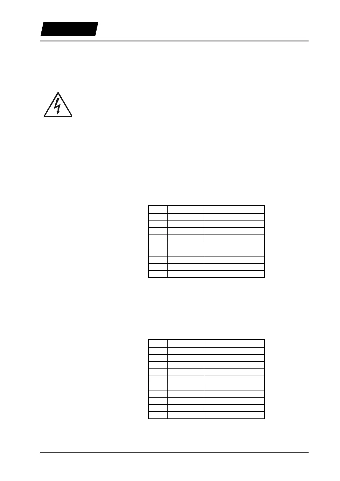
9-pole D-Sub connectors are available on the front of the electronic units of the
E100/E200/E400 series for connecting the actuators.
Table 4-4: E100/E200/E400 pin configuration for the LinMot
P
Only the special LinMot cable (Art. No. 0150-1920) must be used for extension cables.
In applications where the motor cable has to be or moved during operation, the special
trailing chain cable (Art. No. 0150.1927) must be used (max. 10m).
10-pole Mini-Combicon connectors are available on the front of the electronic units of
the E1000/E2000/E4000 series for connecting the actuators.
Table 4-5: E1000/E2000/E4000 pin configuration for the LinMot-P
The lower bit of the motor connector has the pin number 1 (with the unit upright). The
pins are numbered from bottom to top.
E100/E200/E400
Pin Color Signal
1 red Phase 1 +
2 blue Phase 2 +
3 white +5V
4 yellow Sensor Sin
5 black Temperature Sensor
6 pink Phase 1 -
7 gray Phase 2 -
8 brown Ground
9 green Sensor Cos
E1000/E2000/E4000
Pin Color Signal
1 red Phase 1 +
2 pink Phase 1 -
3 blue Phase 2 +
4 gray Phase 2 -
5 white +5V
6 brown Ground
7 yellow Sensor Sin
8 green Sensor Cos
9 black Temperature sensor
10 Shield