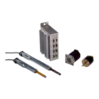
LinMot
Design and Installation
User Manual V1.01 4-16
Message output can be defined via the configuration software to suit your needs
5V supply (digital). Output with a maximal load capability of 50mA
Caution: the pins 4,8,9,10 of Sys1 are exclusively for debugging purposes and must not
be connected.
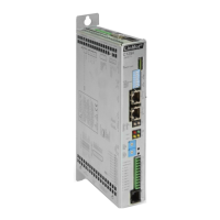
4.5.2 SYS2 connector
The operating states RUN and INIT of the electronic unit are driven through the inputs
of the SYS2 interface. The set values are also given through this port.
Table 4-2: Pin configuration of the SYS2 connector
During normal operation the actuators are turned on and off by means of the RUN
signal.
Data: Galvanically separated input (High level active)
Input voltage: 0…24V DC (max. -10…26V DC)
For signal =0 < 2V DC
For signal =1 > 3.5V DC
Input current: < 20mA (24V)
Input delay: 1.6ms
The initialization of the motors is started.
Data: Galvanically separated input (High level active)
Input voltage: 0…24V DC (max. -10…26V DC)
For signal =0 < 2V DC
For signal =1 > 3.5V DC
Input current: < 20mA (24V)
Input delay: 1.6ms
The inputs TRIG/ANALOG IN A, TRIG/ANALOG IN B, TRIG/ANALOG IN C and
TRIG/ANALOG IN A are used in the states INIT and RUN. In the state RUN these
inputs serve either the direct position value setting with analog signals or the triggering
of reference curves that are stored in the electronic unit. When initializing with a
position sensor, an active edge on this input defines the zero-position.
Data: Analog 0…10V / 100kΩ (10Bit resolution)
Digital max. 24V (Rin 100kΩ)
MSG
+5V / GND
Pin Description Pin Description
1 TRIG / ANALOG IN A 6 TRIG / ANALOG IN C
2 TRIG / ANALOG IN B 7 TRIG / ANALOG IN D
3 RUN + 8 RUN -
4 INIT + 9 INIT -
5 GND
RUN
INIT
TRIG/ANALOG IN