LinMot
Design and Installation
User Manual V1.01 4-19
Only the special LinMot cable (Art. No. 0150-1920) must be used for extension cables.
In applications where the motor cable has to be or moved during operation, the special
trailing chain cable (Art. No. 0150.1927) must be used (max. 10m).
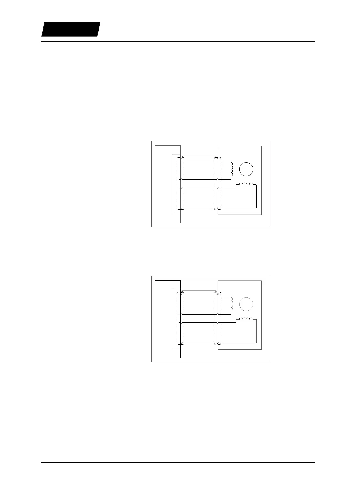
4.6.2 Connecting stepper motors
As stepper motors can only be driven, not controlled, only the two phases need to be
connected to the electronic unit.
When driven by an electronic unit of the E100/E200/E400 family, stepper motors must
be connected as shown in the following figure.
Phase 1
Phase 2
Mot A / Mot B
Mot C / Mot D
Pin
1
6
2
7
+
+
-
-
Rotor
Stepper motor
E100
E200
E400
Figure 4-14: E100/E200/E400 Connection layout for stepper motors
Only shielded cable with a core cross section area of 0.20mm² should be used.
When driven by an electronic unit of the E1000/E2000/E4000 family, stepper motors
must be connected as shown in the following figure.
Phase 1
Phase 2
Mot A / Mot B
Mot C / Mot D
Pin
1
2
3
4
+
+
-
-
Rotor
Stepper motor
E1000
E2000
E4000
Figure 4-15: E1000/E2000/E4000 Connection layout for stepper motors
Only shielded cable with a core cross section area of 0.50mm² should be used.
4.6.3 Connecting inductive loads
Inductive loads can be connected to phase 1 of the electronic unit. The connection
layout corresponds to the one for phase 1 of a stepper motor, as shown in the previous
section.
E100/E200/E400
E1000/E2000/E4000