LinMot
Table of Contents
User Manual V1.01 i
1. Introduction _________________________________________ 1-1
1.1 Used symbols __________________________________________ 1-2
2. Safety notes __________________________________________ 2-1
2.1 Installation____________________________________________ 2-2
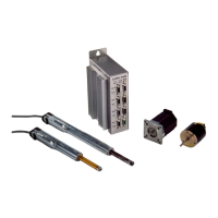
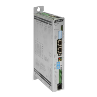
3. System Overview ______________________________________ 3-1
3.1 Drive system LinMot
®
___________________________________ 3-1
3.1.1 Actuator: Linear drive LinMot
®
P ____________________________ 3-2
3.1.2 Actuator: stepper motor LinMot
®
Step_________________________ 3-2
3.1.3 Actuator: electromagnet LinMot
®
Magnet ______________________ 3-2
3.2 LinMot
®
P: a new construction element ____________________ 3-2
3.3 Substitution possibilities of LinMot
®
P _____________________ 3-3
3.4 Technical properties of LinMot
®
P ________________________ 3-4
3.5 Application fields of LinMot
®
P ___________________________ 3-4
3.6 Driving and operating modes of LinMot
®
___________________ 3-5
3.6.1 Driving concept __________________________________________ 3-5
3.6.2 Operation modes _________________________________________ 3-5
3.6.3 Connection to higher-level control systems _____________________ 3-8
3.7 Protection and error behavior ____________________________ 3-9
3.7.1 Internal protection functions ________________________________ 3-9
3.7.2 Monitoring functions ______________________________________ 3-9
3.7.3 Emergency stop possibilities ________________________________ 3-9
3.7.4 Emergency stop through supply interruption ____________________ 3-9
3.8 Operation and configuration ____________________________ 3-10
3.8.1 System configuration _____________________________________ 3-10
3.8.2 Curve generation ________________________________________ 3-11
3.8.3 Monitoring function (digital Oscilloscope) ____________________ 3-12
3.8.4 Error logbook___________________________________________ 3-13
3.9 Customer specific applications __________________________ 3-14
4. Design and Installation ________________________________ 4-1
4.1 Operating modes _______________________________________ 4-1
4.1.1 Analog position setting ____________________________________ 4-2
4.1.2 Analog current setting _____________________________________ 4-3
4.1.3 Two point run____________________________________________ 4-3
4.1.4 Running reference curves___________________________________ 4-4
4.1.5 Set values through the serial interface _________________________ 4-5
4.2 Operating states _______________________________________ 4-6
4.2.1 Operating state “Setup” ____________________________________ 4-7
4.2.2 Operating state “Wait for Disable” ___________________________ 4-7
4.2.3 Operating state “Disable”___________________________________ 4-7
4.2.4 Operating state “Drive Init” _________________________________ 4-7
4.2.5 Operating state “Run” _____________________________________ 4-8
4.2.6 Operating state “Stop” _____________________________________ 4-8
4.2.7 Operating state “Error” ____________________________________ 4-8
4.3 Position monitoring ____________________________________ 4-9
4.3.1 Following error monitoring _________________________________ 4-9
4.3.2 Position range monitoring _________________________________ 4-10