LinMot
Design and Installation
User Manual V1.01 4-23
4.8 HW configuration of the electronic units
The electronic units consist of a signal board and a power board that you can configure
to suit your own requirements.
To configure the boards you must remove the heat sink and open the case. This is done
by removing all the screws. The two boards are kept in place by spacers and connected
by means of post connectors. When opening the unit and handling the electronic boards
the usual care should be taken in observing the necessary measures to prevent
electrostatic discharge that would otherwise damage the boards (ESD-mats, ground
connection, ..).
Further care must be taken in order not to damage or stress either mechanical or
electrical components, as this could lead to malfunction or damage.
Caution: The electronic unit must be completely assembled and closed in its case before
it can be put back into operation.
4.8.1 Signal board configuration
The two electronic unit series E100/E200/E400 and E1000/E2000/E4000 differ only in
the execution of the power board. The signal boards are absolutely identical and for this
reason the explanations in this section are valid for both.
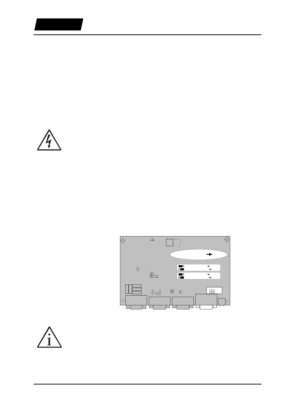
The interfaces to the higher-level control system can be configured on the signal board.
Only the following jumper positions result in usable configurations of the electronic
unit.
Instead of the digital open-collector outputs, relay closers or openers can be configured
to act as outputs.
J101
J102
Sys1Sys2Com
J504
J502
J503
J501
J402
J401
J509
J508
J506
J507
J505
J511
J510
J510: DIG_OUT_OC_4 Pin12.
J510: RELAIS_CLOSER Pin12.
J511: DIG_OUT_OC_3 Pin11.
J511: RELAIS_OPENER Pin11.
DIG_OUT / RELAIS Sys1
Figure 4-18: Configuration SYS1
Hint: If the relay output is needed, it is preferable to use the closer contact, because
when using the opener contact the digital output signal for the position monitoring is no
longer available.
By default the electronic unit is configure for operation with the output signal for the
position monitoring (open collector output) and the relay closer contact.
SYS1 interface