LinMot
Design and Installation
User Manual V1.01 4-6
4.2 Operating states
The operating modes described in the previous chapter have shown how the actuators
can be driven when the electronic unit is on (i.e. when it is in the state RUN). This
chapter gives a description of all the operating states.
The following are the possible operating states of the electronic unit:
SETUP The system is being started
WAIT FOR DISABLE Prevents uncontrolled starting
DISABLE The system is ready to run
DRIVE INIT Initialization of the drives
RUN The motors run
STOP Stop behavior
ERROR Error state
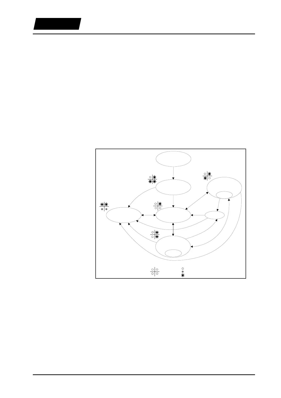
The following figure shows the states and the possible state transitions.
LED off
LED blinking
LED on
LED's
Fault Ready
Stat A
Stat B
RUN
STOP
FREEZE
DISABLEERROR
WAIT FOR
DISABLE
DRIVE INIT
FREEZE
SETUP
Figure 4-7: Operating states
A state change can either be caused by means of the digital control signals to the
electronic unit or, in certain cases by the electronic unit itself (e.g. in case an error
occurs).
The following are the control signals of the electronic unit:
INIT Initialization of the drives
RUN The actuators are powered
FREEZE The actuators maintain the actual position
STOP Change to the operating state Stop
Overview
Control signals