CHAPTER 3: SETTING INTO OPERATION 25
TRYTON 107/112
• Place a spirit-level transversally across the aluminium chassis of the bar-feeder.
Adjusting the screws (B), set the lateral level of the bar feed system.
• Adjusting the central screws (C), set the height of the bar feed system.
• Together with the vertical alignment, proceed with the lateral alignment, by shifting the apparatus.
• When the alignment is satisfactory, tighten all locking screws (E) and nuts (D).
Check the alignment and, if necessary, correct it with the screws (B).
The locking nuts of the levellers, must not be tightened until the bar-feeder has been
anchored to the ground.
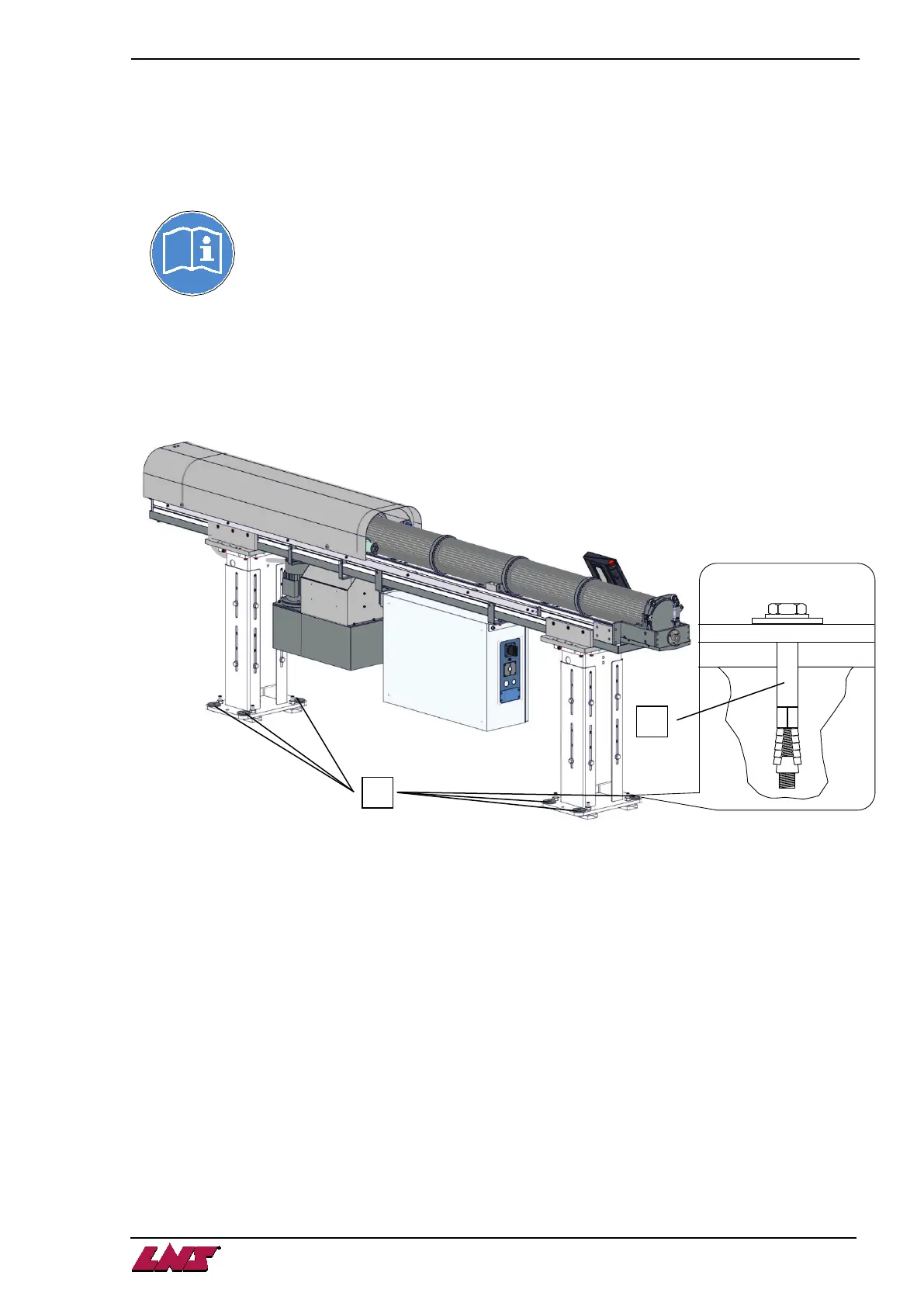
3. ANCHORING TO THE GROUND
Once the bar feed system is in place, and perfectly aligned, it should be anchored to the ground to make it
stable. To accomplish this, 8 anchorage points (A) have been provided.
8 anchorage bolts (B) must be furnished by the client (Minimum M 10 x 100 mm)(Minimum 1/2" x 4").
• Once the anchoring bolts are tightened, check the alignment again, and correct it if necessary
• Tighten the nuts of the leveling screws.
• Remove the red safety screws of the lateral pivoting device (option)
4. CONNECTING
Once the bar feed system has been aligned and anchored to the ground, the bar feeder must be connected
to the interface of the lathe and compressed air needs to be connected.
At this stage, the hydraulic tank may be filled.
• For the electrical connection, please see Chapter 4, Electrics.
• For the pneumatic connection, please see Chapter 5, Pneumatics.
• For filling the tank, please refer to Chapter 6 / Hydraulics
 Loading...