52 CHAPTER 5: PNEUMATIC
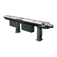
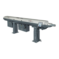
TRYTON 107/112
3. PNEUMATIC VALVE
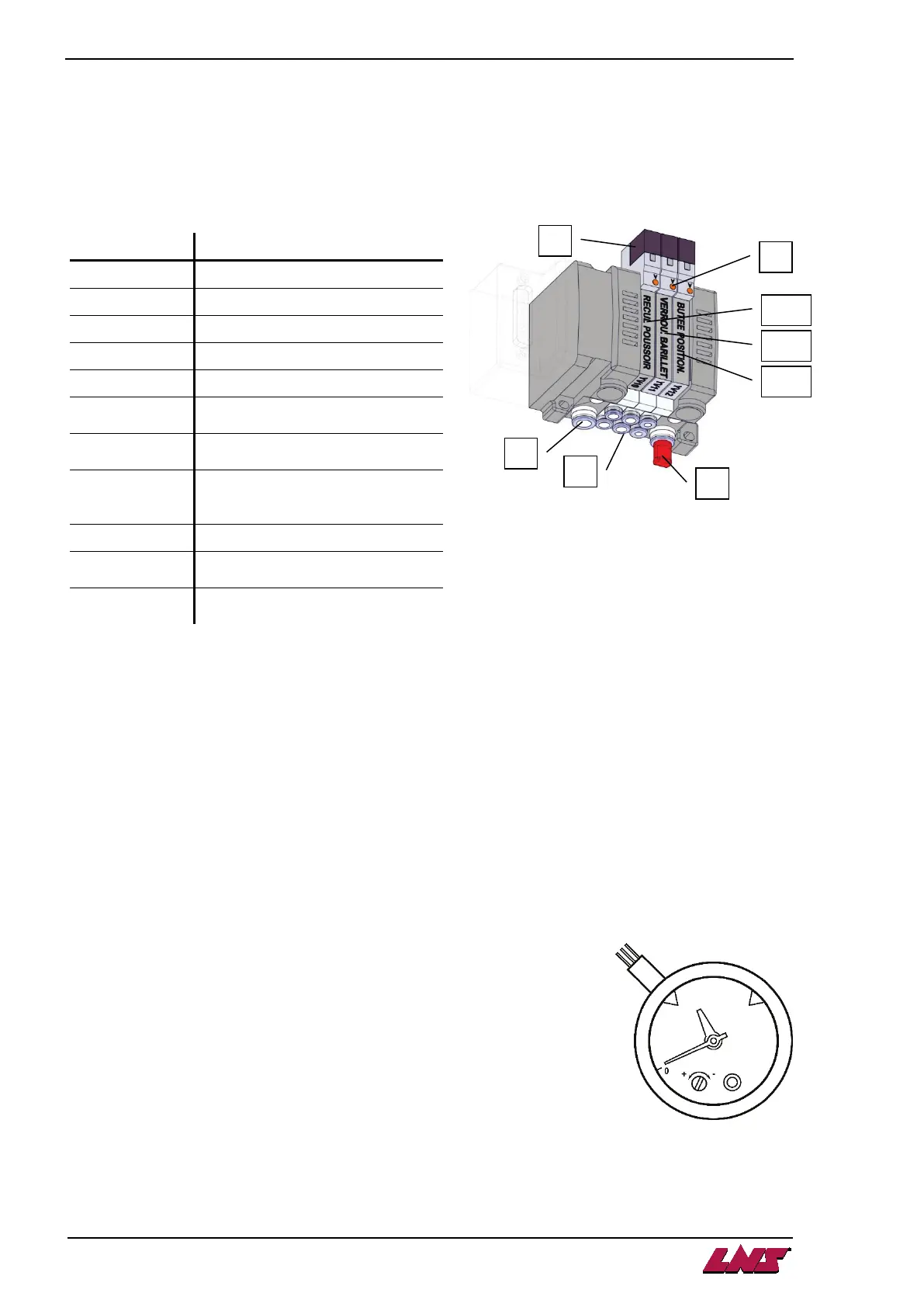
3.1. Description
The pneumatic battery includes the control and monitoring elements of the barfeed system pneumatic circuit.
3.2. Layout of the elements
Designation Description
A Inlets
B Outlets
C Silencer
D Control plug
E Manual activation key
YV10
Electro-valve :
pusher retract cable coupler
YV11
Electro-valve :
barrel unlocking
YV12
position end-stop
YV15 Blocking section feed (option)
YV18
Camshaft stop (option)
(only for cam lathe type)
YV19
Spindle stop (option)
(only for cam lathe type)
3.3. Manual operation
Directly controlled by the PLC, the electro-valves activate the pneumatic cylinders.
By pressing a key (E), the pneumatic cylinders can be activated manually. This manoeuvre may prove to
be useful during tests or maintenance.
When the (E) key is released, the pneumatic cylinder returns to its resting position (except for pneumatic
cylinders activated by 2 electro-valves).
3.4. Air pressure switch
To guarantee an optimal work of the bar feed system, the service pressure must be at least 5 bars (75 Psi).
The pressure switch serves to confirm that this pressure is present and adequate.
The air pressure switch is directly integrated into the pressure gauge.
Set up procedure for the pressure switch:
• Remove the glass of the pressure gauge
• With a screwdriver, turn the setting screw
• Place back the glass
 Loading...