CHAPTER 5: PNEUMATIC 51
TRYTON 107/112
2. AIR FILTERING UNIT
2.1. Description
The air filtering device serves to filter air and to set its pressure before it is distributed into the pneumatic
circuit of the bar feed system.
The air must be furnished at a maximum pressure of 6 bar, and whenever possible, clean and dry.
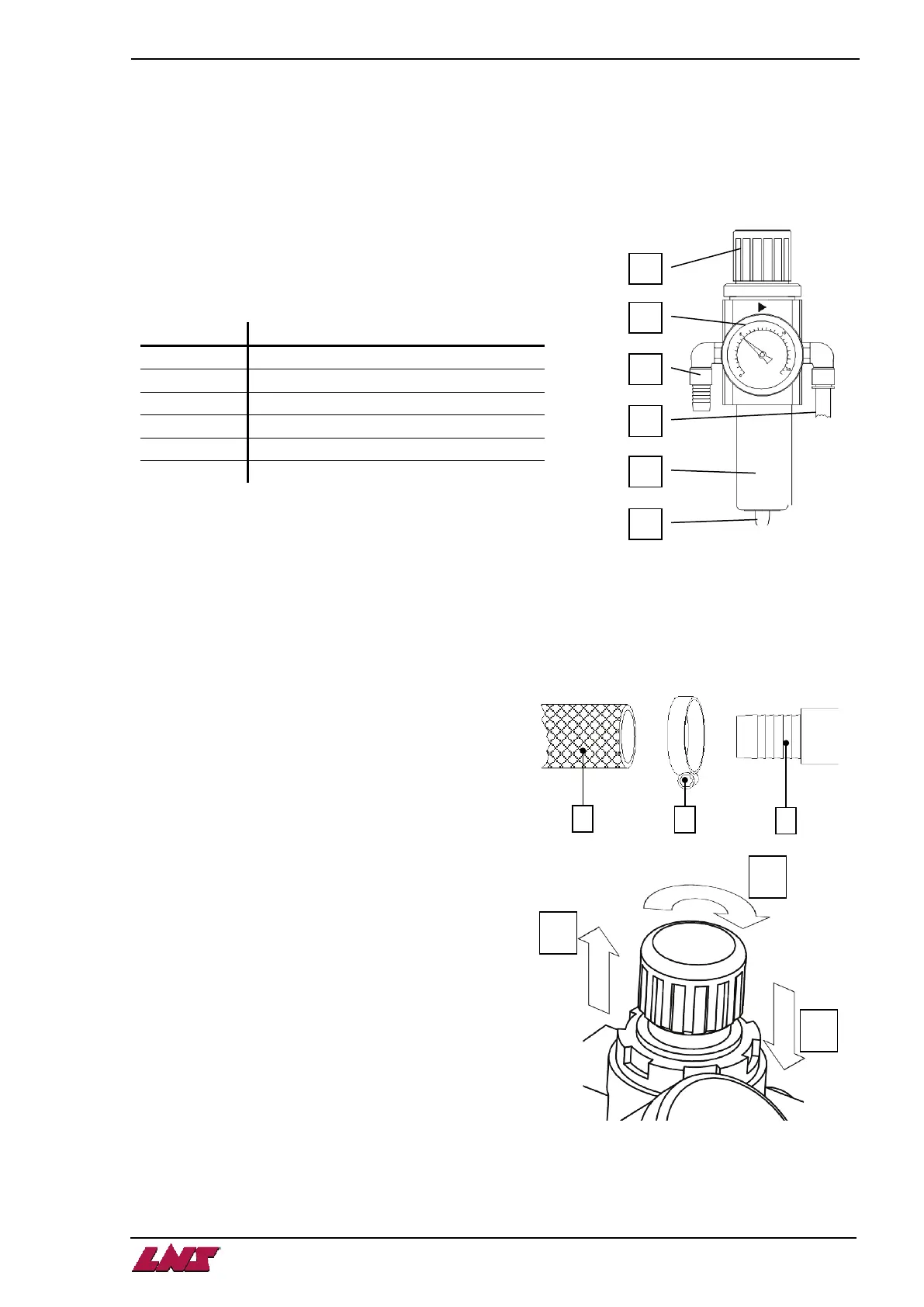
2.2. Layout of the elements
2.3. Connection
The pneumatic connection (C) is located behind the control cabinet.
For the pneumatic connections of the bar feed system, the customer must provide a hose (B) with an inside
diameter of 1/2" (12.7 mm). For USA, 3/8" (9.5mm).
Provide an air hose long enough to allow the complete travel (500 mm) of the retraction system.
When the hose is connected, it should not lie on the
ground because it could become damaged.
1. Place clamp (A) around hose (B).
2. Insert fitting (C) into hose.
3. Tighten the flange (A) to make it airtight.
2.4. Settings
1. Unlock the adjusting knob by pulling it upward.
2. To increase the pressure, turn it clockwise. To
decrease it, turn it in the opposite direction. The
operational pressure should be set at 5 bar.
3. When the settings are done, lock the adjuster by
pushing it downward.
A
B
Pressure gauge with pressure switch
D
Regulated pressure outlet
E
F
Automatic purging