32 CHAPTER 4: ELECTRICS
TRYTON 107/112
4.2. Description of the elements in the electrical cabinet
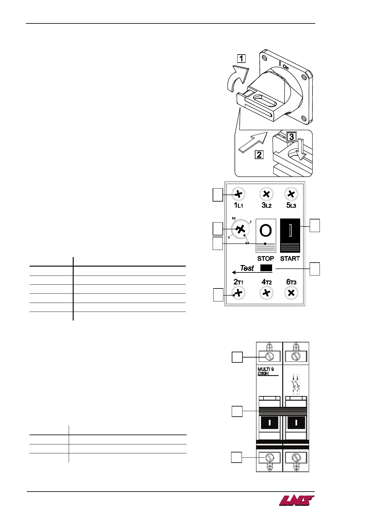
4.2.1. Main power switch QS1
In accordance with the requirements of the international IEC
standards, when the main disconnect switch is at 0 off, it interrupts
the input of the three phases in the control cabinet of the bar feed
system.
To power up the bar feed system, turn (1) the switch handle to the
right, to the Ion position.
To power down , turn the switch to the left, to the 0off position.
The main switch can be locked with a padlock. This way, it is
impossible to turn the bar feed system on.
Push (2) the locking mechanism and insert (3) the padlock into the
opening. Lock the padlock.
4.2.2. Circuit breaker QM1
Circuit breaker QM1 protects the phases, which power the hydraulic
motor.
If the motor requires excessive power, the circuit breaker
activates and push-button (C) STOP is released. For safety
reason, the power supply to the motor is immediately
interrupted.
After having located and repaired the problem causing this
interruption, reset the circuit breaker by pressing the push-
button (F) START.
At the factory, the breaking current is set to 2.5 amperes.
4.2.3. Circuit breaker QF1
Circuit breaker QF1 protects the two phases, which power the
transformer.
Should the latter require excessive power (>4 Amps), the
breaker activates and lever (B) flips down.
The power supply to the transformer is immediately interrupted
to avoid material damages.
After having located and repaired the problem causing this
interruption, reset the lever (B) of the circuit breaker.
A
Power in connecting terminal
B
Setting the breaking current
C
Release button
D
Power out connecting terminal
E
A
Power in connecting terminal
B
Lever on/off
C
Power out connecting terminal