CHAPTER 6: HYDRAULIC 57
TRYTON 107/112
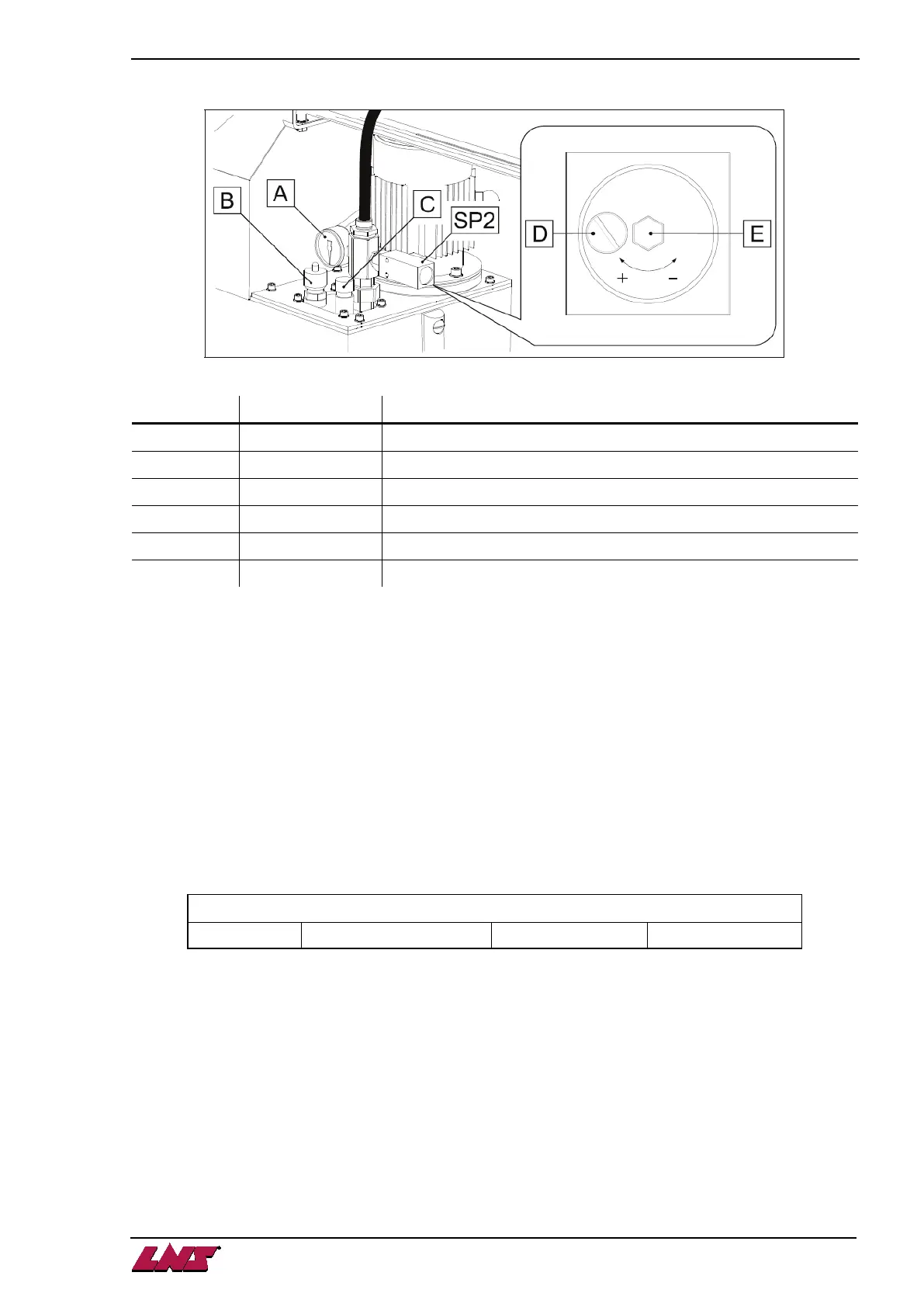
1.3. Hydraulic block
Designation Article nr. Description
A 2.032 Pressure gauge
B 2.064 Pressure regulator
C 2.063 Feed regulator
D - Locking screw
E - Adjusting screw
SP2
44.0179.K0.45
Pressure switch
1.4. Adjustment
The pressure is constantly monitored by a pressure switch (SP2) set at the factory at a point of release of
0.5 bar. It may be adjusted, if necessary, as follows:
1) With a screwdriver, unscrew the locking screw (D).
2) Insert a hex head wrench (5mm) into the center of the pressure switch (E).
By turning clockwise, the release of the pressure switch will take place at a pressure higher than the
original setting. Turning in the opposite direction, will produce the reverse.
3) When the adjustment is completed, retighten the locking screw (D).
1.5. Filling and draining
The bar feed system is delivered without oil. 25 liters of hydraulic oil of the type indicated below must be
provided by the client. The oil must be poured directly into the hydraulic tank through the filling openings.
Viscosity equivalency table
ISO 100 100 mm2/s (cSt) à 40°C DIN 68 8°E à 50°C
Consult your supplier who will recommend the correct oil for you.
To drain the hydraulic tank, place a container with sufficient capacity (minimum: 25 liters) underneath the
tank, and unscrew the drain plug.
Please refer to Chapter 9/Maintenance for cleaning the filter.