78 CHAPTER 8: OPERATION
TRYTON 107/112
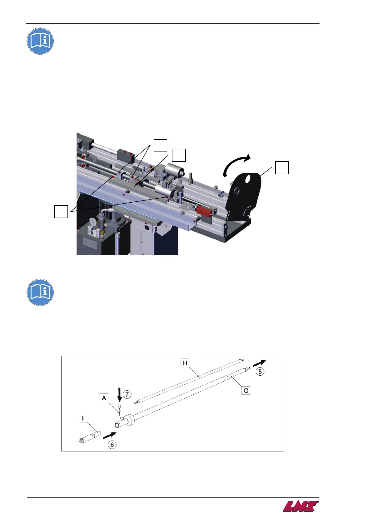
If the reduction tube can be extracted from the rear of the bar-feeder, swing out the rear
protective plate (I), and continue with point 5 below.
If there is any obstacle (wall, machine, etc.) preventing the removal of the reduction tube at the rear,
proceed as follows:
• Undo the fixing screws (K) and remove the guide (L).
• Loosen the screws (M) that hold the connector in the bearings.
• Extract the connector sideways then proceed with the replacement of the reduction tube (G) as
explained in points 5 to 7.
Then install the connector on the bearings and fix with the screws (M). Refit the guide (L).
Pushers of 12.7 mm diameter have no reduction tubes.
5) Extract the reduction tube (G) with the pusher to the inside, then insert the new reduction tube (H).
Fit the cable (E) to the new pusher, reassemble the connector block (D) and secure it with the bolt
(C).
6) Fit the new ferrule (I).
7) Secure the ferrule with the cotter-pin (A).
8) More the connector to its rearmost position with the stationary control.
9) Index the barrel by one tube by pressing the LOAD button on the stationary control