LPKF Laser & Electronics AG | V. 1.0
Fig. 40: Defining the front left corner
The processing head moves to the front left corner.
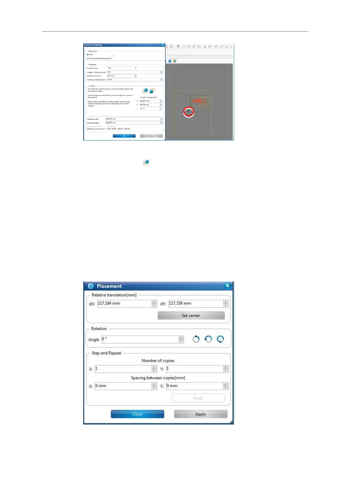
9. Click on the button in the dialog Material settings.
The material area is adapted to the material.
10. Click on [OK].
The phase Placement is started.
The material settings have been defined.
The layout can be copied and placed freely on the base material for economic usage
of the PCB material depending on the size of the layout and the size of the base
material.
Placing the layout
1. Enter the values for the desired position into the fields dX and dY. You can also
move the toolpaths in the machining view using the mouse.